
TM 11-4625-168-15
TM5840-328-15-24
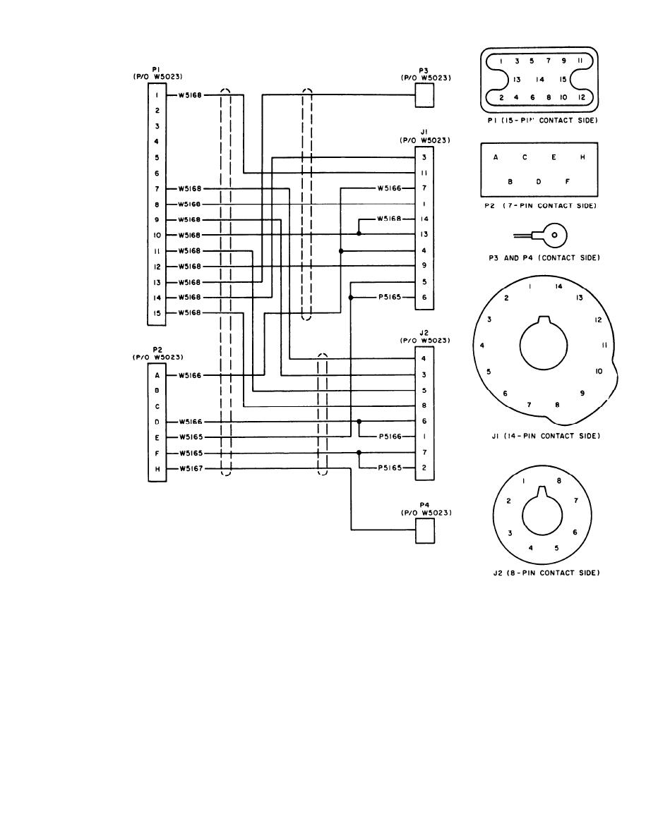
Figure 7-15. Special Purpose Cable Assembly CX-10443/PPS-5, schematic diagram.
insert flange sleeve between braid and
With knife, chamfer end of Teflon
c a b l e dielectric until flange rests
dielectric.
firmly against braid.
(8) T r i m braid to diameter slightly
(7) Hold cable jacket with emery cloth
smaller than flange.
(to keep jacket from slipping), and
7-15
AGO 7918A


 Previous Page
