Home
Download PDF
Order CD-ROM
Order in Print
Home
>
Test Facility Manuals and other related material
>
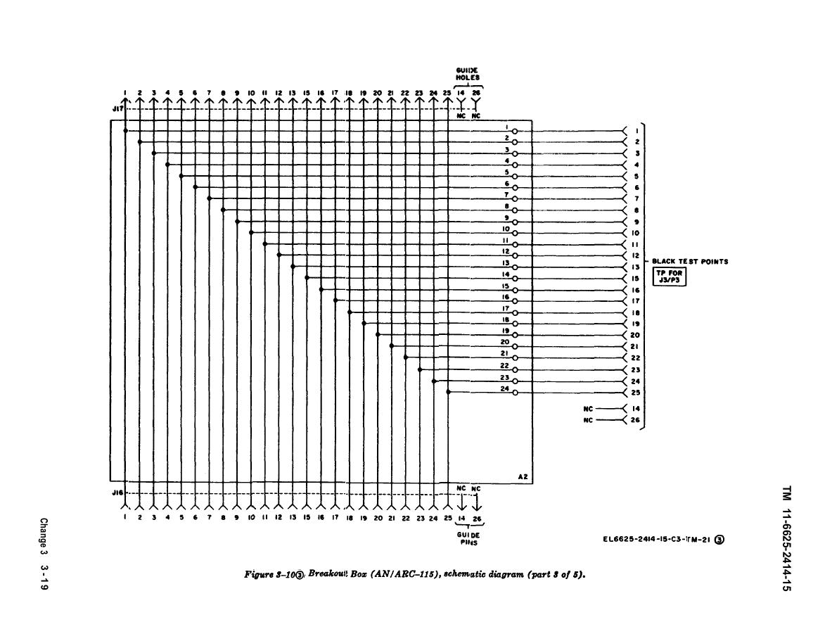
> Figure 3-10. Breakout box (AN/ARC-l15), schematic diagram (part 3 of 5).
Figure 3-10. Breakout box (AN/ARC-l15), schematic diagram (part 2 of 5).
Figure 3-10. Breakout box (AN/ARC-l15), schematic diagram (part 4 of 5).
TM-11-6625-2414-15 Test Facilities Kit MK-1191/AR Manual
Page Navigation
41
42
43
44
45
46
47
48
49
50
51


 Previous Page
