
TM 11-6625-1696-12
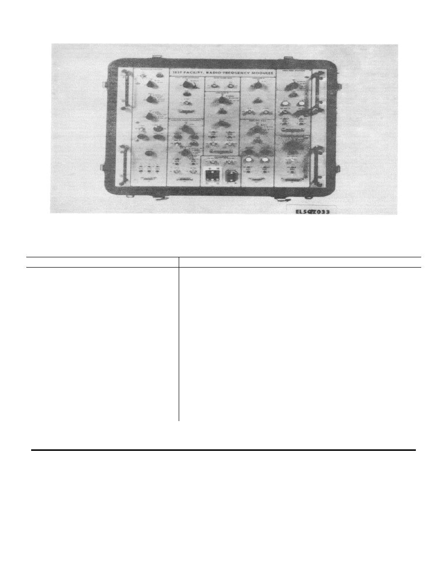
Figure 3-7. Test Facility, Radio Frequency Modules, Front Panel.
3-41. REGULATOR VOLTAGE Section Controls, Indicators, and Connectors
Controls/indicators
Function
Switch S1
Connects + 13 volts dc supply (when applied to connectors JI and J2)
to in-
ternal voltage regulator circuit.
SUPPLY indicator
Lights when power is applied to AUT.
Switch S2
Selects desired regulated output voltage. 6.4 volts dc, 7.2 volts dc or
8.0
volts dc.
Switch S3
Connects test conditions and metering facilities to selected AUT
Switch S4
Provides various loads to an AUT.
Switch S5
Simulates output impedance of AN/IGRC- 103(V) transmitter power
supply to an
AUT, during short-circuit testing.
Switch S6
Applies a dummy load to voltage regulator when setting output voltage.
100 mA SET control
Adjusts current from +28 volts supply to 100 mA.
INPUT V ADJ control
Adjusts 6.4 volt reference output from voltage regulator.
MAX CUR control
Checks the voltage feedback of an AUT.
Connectors J 1 and J2 SUPPLY
Connect + 13 volt dc supply input.
Connectors J3 and J4 METER
Current monitor points for AUT.
Connectors J5 and J6 METER
Voltage monitor points for DRIVER or OUTPUT circuits from AUT.
Connector J7
Connects AUT to test panel.
3-23

 Previous Page
