Home
Download PDF
Order CD-ROM
Order in Print
Home
>
Test Facility Manuals and other related material
>
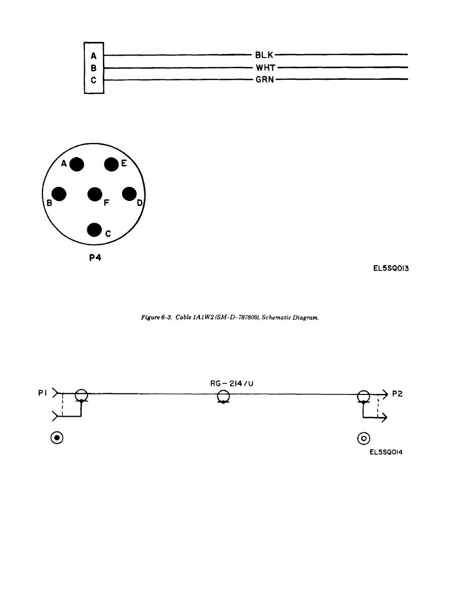
> Figure 6-4. Cables 1A1 W3 and W4 (CG -3750/TPM-24(V), Schematic Diagram.
Figure 6-2. Cable AI W1 (SM-D-787808), Schematic Diagram.
Figure 6-6. Cables 1A1 W6, W7, and W8 (CG-3754/TPM-24 (V)), Schematic Diagram.
TM-11-6625-2398-14-4 Test Facilities AN/TPM-24(V)4 (NSN 6625-01-086-5129) Manual
Page Navigation
25
26
27
28
29
30
31
32
33
34
35
TM
11-6625-2398-14-4
Figure
6-4.
Cables
1A1
W3
and
W4
(CG
-3750/TPM-24(V),
Schematic
Diagram.
6-6


 Previous Page
