
TM 11-6625-2398-15-2
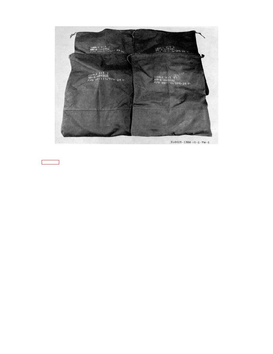
Figure 1-5. Canvas bag 1A2 thru 1A5.
e. Interface Adapter Unit 1A1A1. The interface
addition, there are switches for controlling power and
providing seven enables to the IFF set. The front panel
adapter unit (fig. 1-6) contains eight RF connectors, and
also contains controls for antenna rotation and two dials
13 multipin connectors mounted on the rear panel.
which provide azimuth readout. The front panel is
These connectors provide for connecting the interface
attached to the main chassis by 14 captive screws and
adapter unit to the IFF set. On the front panel, there are
the rear panel is held by 18 captive screws. Two
eight RF test jacks which provide for monitoring IFF
carrying handles are provided on the front panel.
signals using external test equipment. There are also
five test jacks for monitoring IFF azimuth data. In
1-10

 Previous Page
