TM 11-6625-2398-15-2
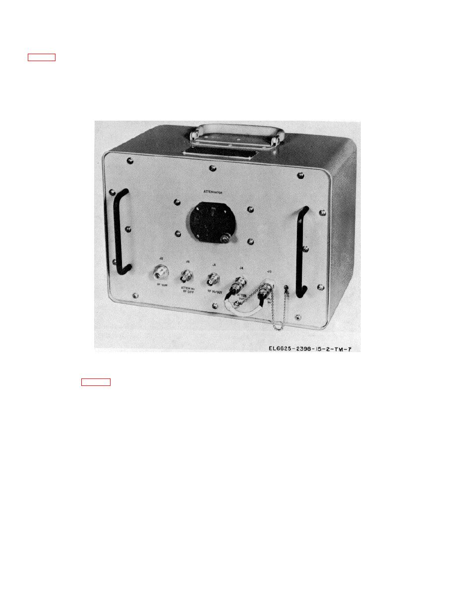
f. Hybrid attenuator 2A1. The hybrid attenuator
1090 MHz when the attenuator dial is set at 0 db; also
listed are ATTENUATOR insertion losses at 1030 and
1090 MHz for ATTENUATOR dial settings of 0, 3, 6, 9,
variable attenuator assembly. These assemblies are
12, 15, 20, and 25 db. Connectors on the front panel of
combined in a single unit with a carrying handle on top of
the unit are used to couple the hybrid junction and/or the
the case. A card, containing calibration data pertaining
attenuator into a test setup using the test facilities set
to the hybrid junction and attenuator insertion losses, is
cables.
attached to the handle. The card lists the sum channel
and difference channel insertion losses at both 1030 and
Figure 1-7. Hybrid attenuator 2A1.
g. Antenna Pedestal .Mount 1A7. The antenna
block that supports the antenna pedestal while the IFF
set is being tested.
pedestal mount (fig. 1-8) consists of a metal mounting
1-12


 Previous Page
