
TM 11-6625-1683-15
ciently to avoid obstructing service opera-
panel. The screws are accessible
tions.
from the top of the panel.
d. Shaping Network. The shaping network
(c) Remove four screws securing the
consists of three nonrepairable component:
side brackets to the partition.
squaring amplifier Z1, one-shot multivibrator
(d) Remove the power converter as-
Z2, and drive amplifier Z3 (fig. 7-1). These
sembly.
three components are mounted on a socket
Note. Removal of the internal power
assembly at the left side of the test panel. To
converter assembly will also provide access
remove any one of these components, detach
to parts on the upper central area of the
the covering shield of each, held in place by a
test panel that normally are hidden by the
bayonet-type latch. Extract the component
converter. For examination or replacement
from its socket by a direct outward pull. Do not
of such components, it is not necessary to
rock or apply strong force, or distortion of the
disconnect the three leads to the interior
contact pins may result, When installing the
power converter. Enough slack is allowed
in the leads to permit the converter to be
components, be sure that the proper type is
mechanically detached and displaced suffi-
returned to the designated socket.
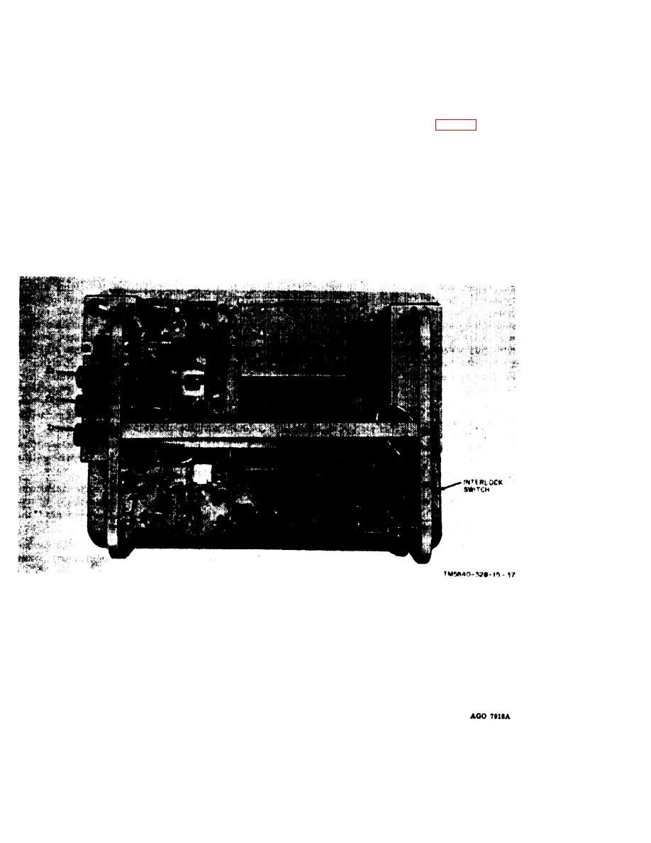
Figure 7-1, Test Panel SB-3004/PPS-5, bottom view.
7-2

 Previous Page
