Home
Download PDF
Order CD-ROM
Order in Print
Home
>
Test Facility Manuals and other related material
>
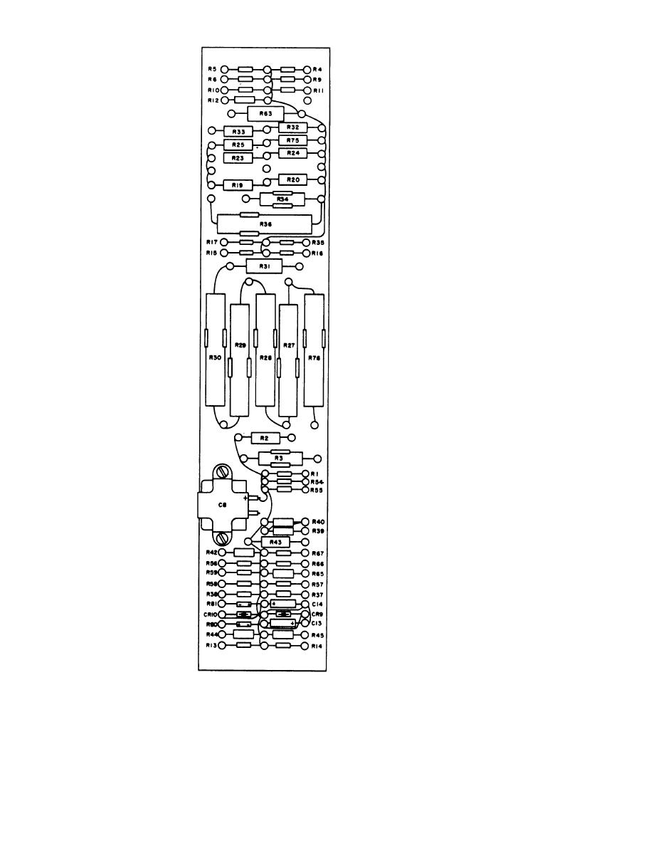
> Figure 7-3. Load resistor board assembly E1, component location.
Figure 72. Electrical Test Panel SB-3004/PPS-5, rear view, internal power converter removed
Figure 7-4. Internal power converter, PS5001, cover removed from shield.
TM-11-6625-1683-15 Test Facilites Kits MK-980/PPS-5 (NSN 6625-00-933-9980) and MK-980A/PPS-5 (NSN 6625-00-453-5667) Manual
Page Navigation
55
56
57
58
59
60
61
62
63
64
65
C 7, TM
11-6625-1683-15
TM5840-328-15-C7-52
Figure
7-3.
Load
resistor
board
assembly
E1,
component
location.
7-4


 Previous Page
