
TM 11-6625-1683-15
Notes:
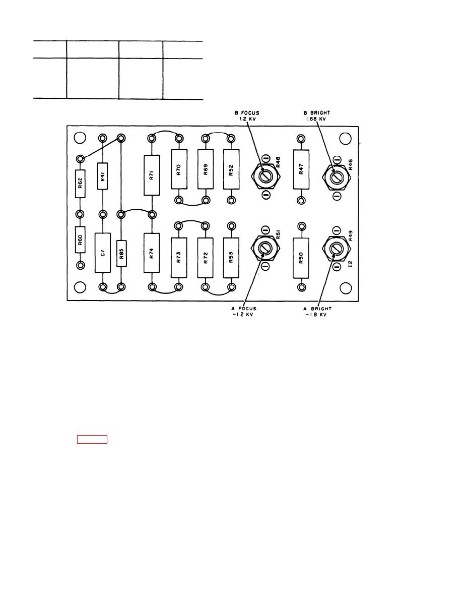
Voltage
Readout
Reference
Function
designation
point
setting
1. All readings referred to ground.
2. CRT TEST push switch S17 must be pressed and
1.68 kv
B brightness
R46
J16-12
held to obtain readings.
B focus
1.2 kv
R48
J16-14
A brightness
R49
1.8 kv
J16-7
R5l
A focus
1.2 kv
J16-11
TM5840-328-15-43
F i g u r e 7-7. Compont board assembly.
Section Ill. CABLE REPAIR
If cable repair is necessary, be careful not
contact designations on the connector
to damage any re-usable portion of the assem-
face. This is important in order to
bly. Do not use excessive heat when unsoldering
maintain correct orientation of the
leads, and avoid spattering solder over con-
connector with respect to its mate.
nector surfaces. Be sure that connector pins
(3) With a spline-type wrench, loosen
are not bent or distorted.
the setscrews in the knurled knobs at
the rear of the connector.
7-5. Cable Assembly CX-10431/PPS-5
(4) Remove the knobs and the small spac-
ing washers.
a. Detach either connector from the cable
as follows:
(5) Withdraw the molded connector body
(1) Loosen two strain clamp screws.
from the shell, carefully feeding the
(2) Note the locations of the male and
cable along through the shell. Avoid
female locking screws relative to the
strains.
7-8
AGO 7918A

 Previous Page
