
TM 11-6625-1683-15
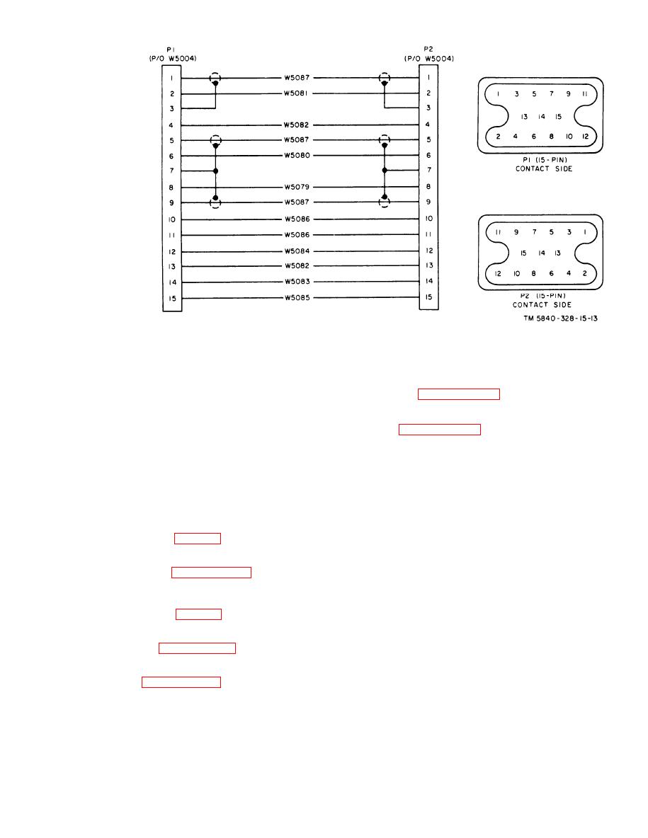
Figure 7-13. Special Purpose Cable Assembly CX-10432/PPS-5, schematic diagram.
c. To detach large connector from cable, re-
connector body, clinching and solder-
fer to paragraph 7-10a(1) through (6).
ing each lead as inserted.
(5) Slip plastic sleeves along wire and
d. To replace large connector on cable, refer
over terminals.
to paragraph 7-10b(1) through (7).
(6) Reassemble each connector, making
e. To replace small crt socket (not salvage-
certain that cable clamp is secure.
able), proceed as follows:
(7) Check for correctness, continuity, and
(1) Clip the wire leads as close to the
shorts before returning the cable to
socket as possible.
service.
(2) Strip each lead end one-eighth inch.
7-11. Cable Assembly CX-10439/PPS-5
(3) S l i p 3/8-inch lengths of plastic
sleeving over each lead and place it
in a r e t r a c t e d position so that
The repair procedure is the same as that
stripped ends of wires are clear.
given in paragraph 710.
(4) The connector has two plastic sec-
tions with metal contact inserted in
7-12. Cable Assembly CX-10443/PPS-5
the molded section. Solder each wire
to the appropriate contact.
a. To detach small connector from cable, re-
(5) Adjust the plastic sleeve on each wire
fer to paragraph 7-5a(1) through (8).
to cover the tab end of the contact.
(6) Cement the plastic backplate to the
b. To replace small connector on cable, refer
reverse side of the molded section,
to paragraph 7-5b(1) through (7).
7-13
AGO 7918A

 Previous Page
