TM 11-6625-1683-15
TM5840-328-15-20
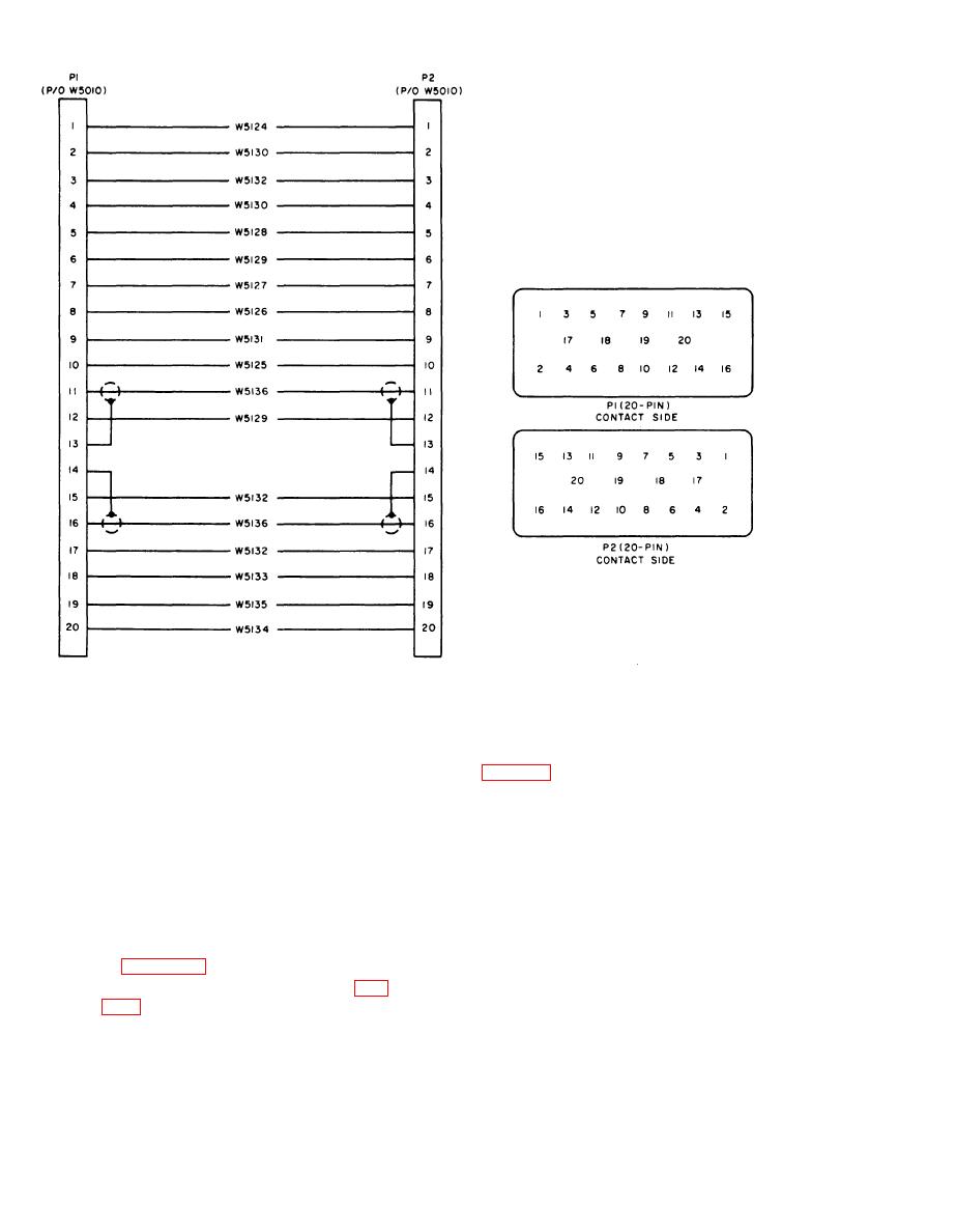
Figure 7-14. Special Purpose Cable Assembly CX-104S9/PPS-5, schematic diagram.
making certain that the keyways in
7-13. Rf Cable Assembly CG-3353/U
each are in alignment.
f. Replace the large crt socket as follows:
a. BNC Connector Plug. Replace the connec-
(1) Follow the procedures given in e(l)
tor as follows:
through (5) above.
(1) Cut cable as close to connector as
(2) Affix plastic backplate to molded sec-
possible.
tion with two machine screws, nuts,
(2) Cut cable off square.
and washers.
(3) Strip outer Teflon jacket to braid for
g. Replace the cable as follows:
distance of one-half inch.
(4) Slip clamp nut, washer, gasket, and a
(1) Refer to circuit and material details
in figure 715.
second washer back on cable.
(2) Check circuits for conformity (fig.
(5) Smooth braid out over washers, and
bend braid back.
7-14
AGO 7918A


 Previous Page
