
TM 11-6625-1683-15
the locating holes are aligned with the index-
b. Female Connector. Replace connector by
ing hole in the flange of the shell.
use of the procedure in a above.
c. Cable, TReplace cable as follows:
c. Cable. Replace cable as follows:
(1) Remove connectors from cable as in-
(1) Remove connectors from cable as in
structed in a(1) through (4) above.
strutted in a(1) and (2) above.
(2) Connect conductors of cable to con-
( 2 ) Install new cable as instructed in
tacts of connectors, and reassemble
a(3), (4), and (5) above.
connectors a s i n s t r u c t e d i n (5)
through (9) above,
7-20. Special Purpose Electrical Cable
Assembly CX-10438/PPS-5
7-19. Special Purpose Electrical Cable
Assembly CX-10437/PPS-5
a. Male Connector. Replace male connector
as follows:
a. Male Connector, Replace connector as
follows:
(1) Note dimensions of epoxy material.
(1) Remove epoxy potting material from
(2) Remove epoxy material,
connector plate assembly, and disas-
(3) Remove indexing tab by removing
semble plate assembly, (Note location
rivets that hold it to printed-circuit
of connector pin A with respect to
board.
plate, )
(4) U n s o l d e r cable conductors from
board.
contacts.
(5) (Solder replacement connector into re-
(3) Solder cable conductors to contacts
placement printed-circuit board.
of replacement connector,
(4) Reassemble connector to plate assem-
(6) Rivet indexing tab to printed-circuit
bly, orienting pin A of connector
board on same side of board as con-
properly to plate,
nector.
TM5840-328-15-18
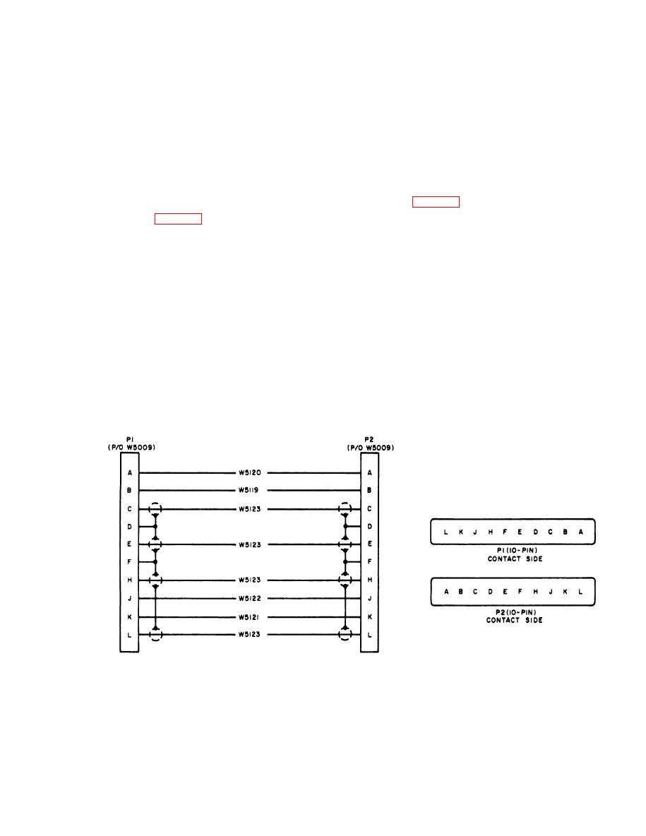
Figure 7-21, Special Purpose Electrical Cable Assembly
CX-10437/PPS-5, schematic diagram.
AGO 7918A
7-19

 Previous Page
