
TM 11-6625-1683-15
(6) Embed connectors in epoxy of sizes
(3) U n s o l d e r cable conductors from
noted in (2) above, with threaded in-
printed-circuit boards.
serts correctly located.
(4) Unsolder printed-circuit board ter-
(7) Install connectors in plate assembly
minals from connector terminals,
with connectors correctly located
(5) S o l d e r replacement connectors to
with respect to index notch.
printed-circuit boards.
b. Female Connector. Replace connector as
(6) Solder cable conductors to terminals
follows:
of printed-circuit boards.
(1) Note relationship of connectors and
(7) Embed connectors in epoxy of sizes
t h e i r contacts with respect to the
noted in (2) above, with threaded
plate assembly; disassemble the plate
inserts correctly located.
assembly.
(8) Install connectors in plate assembly,
(2) Note dimensions of epoxy blocks; re-
with connectors located as noted in
move epoxy from connectors. (Sal-
vage threaded inserts.)
(1) above.
TM5840-328-15-21
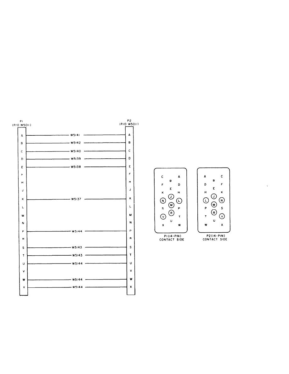
Figure 7-25.
S p e c i a l Purpose Cable Assembly CX-10440/PPS5, schematic diagram.
AGO 7918A
7-22

 Previous Page
