TM 11-6625-1683-15
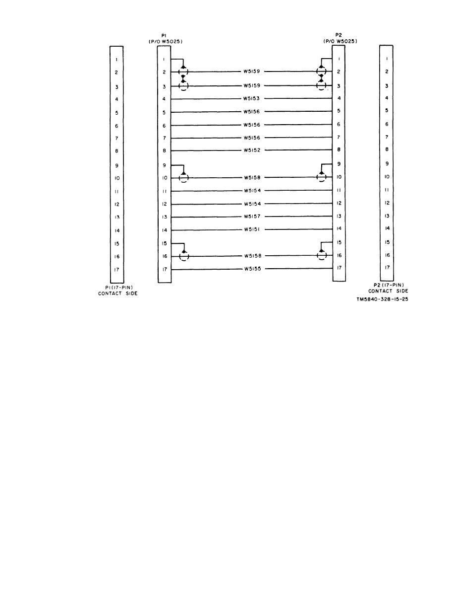
Figure 7-32. Special Purpose Branched Cable Assembly
CX-1044/PPS-5,
schematic
diagram.
b. Female Connector. Replace connector as
(2) Remove epoxy material.
follows:
(3) Remove indexing tab by removing
(1) Note dimensions of epoxy material
rivets that hold it to printed-circuit
board.
and location of inserts.
(2) Remove epoxy material and rubber
(4) U n s o l d e r cable connectors from
board.
cushioning from around contact ter-
minals; salvage the inserts.
(5) Solder replacement connector into
replacement printed-circuit board.
(3) Unsolder cable conductors from con-
nector terminals.
(6) Rivet indexing tab to printed-circuit
board on opposite side of board from
(4) Solder cable conductors to replace-
connector.
ment connector.
(7) Solder cable conductors to printed-
rubber
(5) Install
new
circuit board terminals.
around connector terminals.
(8) Embed connector in epoxy material
(6) Embed connector in epoxy material
with dimensions noted in (1) above.
with dimensions noted in ( 1 ) above.
AGO 7918A
7-27


 Previous Page
