
TM 11-6625-1683-15
c. Cable. Replace cable as follows:
ment plug.
(1) Remove connectors from cable as out-
lined in a(l) through (4) and b(l),
(6) Screw sections of plug together.
(2), and (3) above.
c. Pin Plug (on Coaxial Cable). Replace the
(2) Connect replacement cable to con-
pin plug as follows:
nectors as outlined in a(5) through
(1) Unscrew plastic insulating grip from
(8) and b(4), (5), and (6) above.
plug.
(2) Unsolder center conductor of coaxial
7-32. Special Purpose Branched Electrical
cable from tip of plug.
Cable Assembly CX-10485/PPS-5
(3) Remove plug.
(4) Slip plastic insulating grip of re-
a. Miniature Coaxial Connector. Replace the
placement plug on coaxial cable.
connector as described in paragraph 713a.
b. Pin Plug (on Rubber-Covered Wire).
coaxial cable to tip of replacement
Replace the pin plug as follows:
plug.
(1) Unscrew plastic insulating grip from
(6) Screw sections of plug together.
plug.
d. Coaxial Cable. Replace the coaxial cable
(2) Unsolder rubber-covered wire from
as follows:
tip of plug.
(3) Remove plug.
(1) Note length of cable.
(4) Slip plastic insulating grip of replace-
(2) Remove pin plug from cable as de-
ment plug on wire.
scribed in c(l), (2), and (3) above.
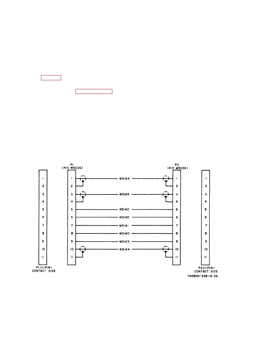
Figure 7-33. Special Purpose Branched Cable Assembly
C X - 1 0 4 4 5 / P P S - 5 , schematic diagram.
AGO 7918A
7-28

 Previous Page
