
TM 11-6625-1683-1S
(3) Remove coaxial connector from cable
(15) Screw pin and plug sections to-
by disassembling the connector body
gether.
and unsoldering the center conductor
e. Rubber-Covered Wire. Replace the rubber-
of the cable from the connector con-
covered wire as follows:
tact.
(1) Note length of wire.
(4) Remove the shrink sleeving from the
joint of the coaxial cable and the
(2) Remove pin plug from wire by un-
rubber-covered wire.
screwing plastic insulating grip from
(5) Unsolder shield of coaxial cable from
pin plug and unsoldering the contact
wire.
pin from the wire.
(6) C u t replacement coaxial cable to
(3) Remove shrink sleeving from joint of
length noted in (1) above.
wire and coaxial cable.
(7) Install coaxial connector on replace-
(4) Unsolder the wire from the shield
ment coaxial cable as described in
of the coaxial cable.
(5) Cut new wire to length noted in (1)
(8) At the midpoint of the coaxial cable,
above.
strip away one-quarter inch of the
outer jacket.
(6) Strip back insulation from one-half
inch from end of wire.
(9) W r a p end of rubber-covered wire
around the exposed one-quarter inch
(7) Wrap end of wire around exposed
of coaxial cable shield, and solder the
1/4-inch length of shield on coaxial
wire to the shield.
cable.
(10) Slip new shrink sleeving (about 1-
(8) Solder wire to coaxial cable shield.
inch length) over joint.
(9) Remove the pin plug from the coaxial
(11) Cut off outer jacket and braid one-
cable as described in C (1), (2), a n d
half inch from other end of cable.
(3) above.
(12) S t r i p center insulation back one-
(l0) Slide new shrink sleeving (about 1-
quarter inch from end of cable.
inch length ) over the joint.
(13) Slip plastic insulating grip of pin
plug over cable.
(11) Install pin plug on coaxial cable as
described in c(4), (5), and (6)
(14) Solder center conductor of coaxial
cable to contact pin.
above.
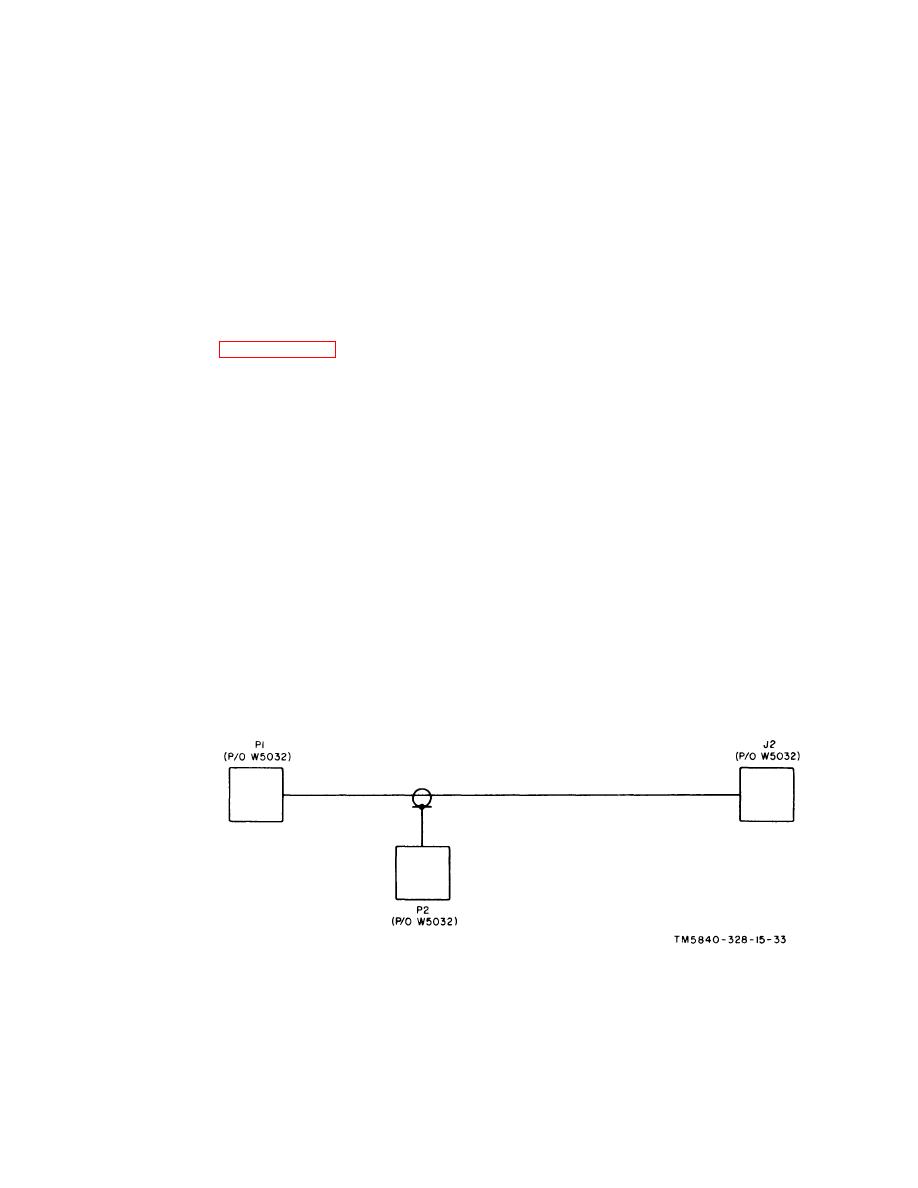
Figure 7-34. Special Purpose Branched Cable Assembly
CX-104485/PPS -5, schematic diagram..
7-29

 Previous Page
