
C 3, TM 11-6625-1683-15
TM5840-328-15-16
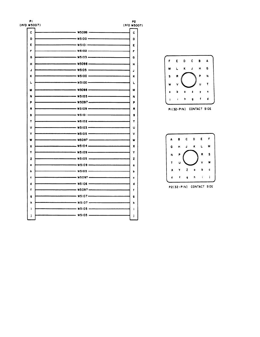
Figure 7-20. Special Purpose Electrical Cable Assembly CX-10435/PPS-5, schematic diagram.
and discard jackscrew and retaining
(8) Replace epoxy bead to secure connec-
ting.
tor to shell,
(9) Replace rubber sealing bead at flange
( 6 ) Solder conductors to replacement
end of shell.
connector.
( 7 ) Slide shell over connector; make
b. Female Connector. Replace female con-
sure indexing pins align with index-
nector by using the procedure given in a
ing hole in flange of shell,
above, except that there is no jackscrew, and
7-18

 Previous Page
