TM 11-4625-1683-15
C2
7-15. Rf Cable Assembly CG-3355/U
(9) Trim cable dielectric and center con-
ductor to length of 0.135 inch from
flange.
a. Miniature Connector Plug. To replace min-
(lo) Trim dielectric to 0.040 inch from
iature connector plug, follow the procedure
flange,
given in paragraph 713a.
(11) Slip insulator over dielectric until it
b. Cable. The cable can be repaired by cut-
rests against flange.
ting it shorter and reconnecting it to the min-
(12) Slip contact over wire, and solder
iature connector plug, but its length cannot
with minimum heat.
be less than 3. inches from adapter end.
(13) Slip body over pin, and press wash-
c. Adapter. To repair adapter, remove epoxy
ers, gasket, and clamp into body;
potting, replace resistors as necessary, replace
tighten clamp nut.
coaxial contact, if necessary, strip back coax-
ial cable three-eights inch, solder braid of
b. Miniature Connector Plug. To replace min-
cable to inside wall of adapter, and solder
iature connector plug, use the procedure given
cable conductor to standoff inside adapter.
in a above.
Refill adapter with epoxy resin.
c. Cable. Replace cable as follows:
(1) Remove damaged cable from connec-
7-16. Special Purpose Cable Assembly
tor by disassembling connectors and
CX-104341PPS-5
unsoldering cable from contacts.
(2) Install new cable on connectors ( a
Replace connectors as follows:
above).
a. Remove boot from connector.
7-140 Rf Cable Assembly CG-3354/U
b. Remove retaining screws.
c. Disassemble connector.
The repair procedure is the same as that
given in paragraph 713.
TM 5840-328-15-35t
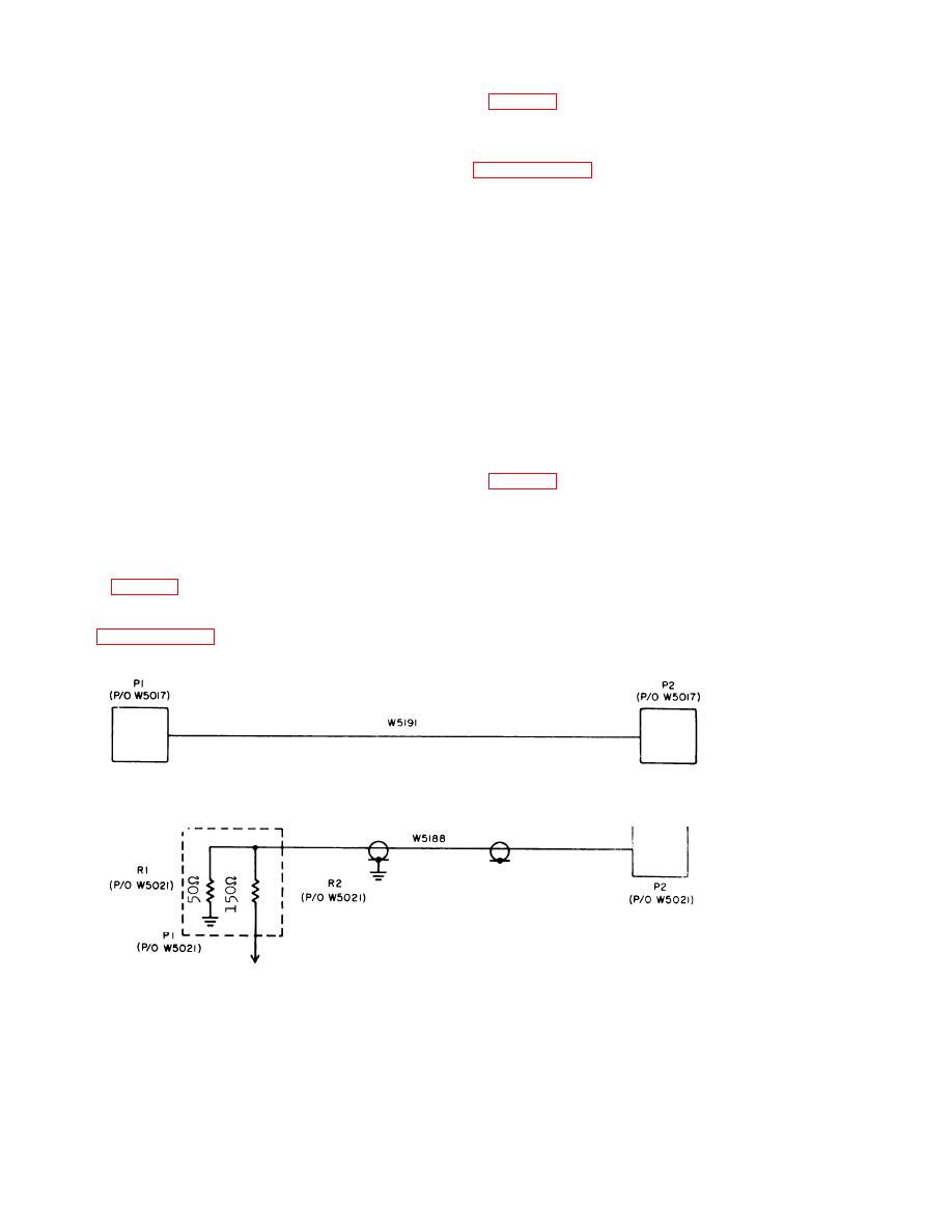
Figure 7-16. Special Purpose Cable Assembly CX-3353/PPS-5, schematic diagram.
TM 5840-328-15-9
Figure 7-17. Rf Cable Assembly CG-3355/U, schematic diagram.
7-16
AGO 7918A


 Previous Page
