TM 11-6625-1683-15
TM5840-328-15-17
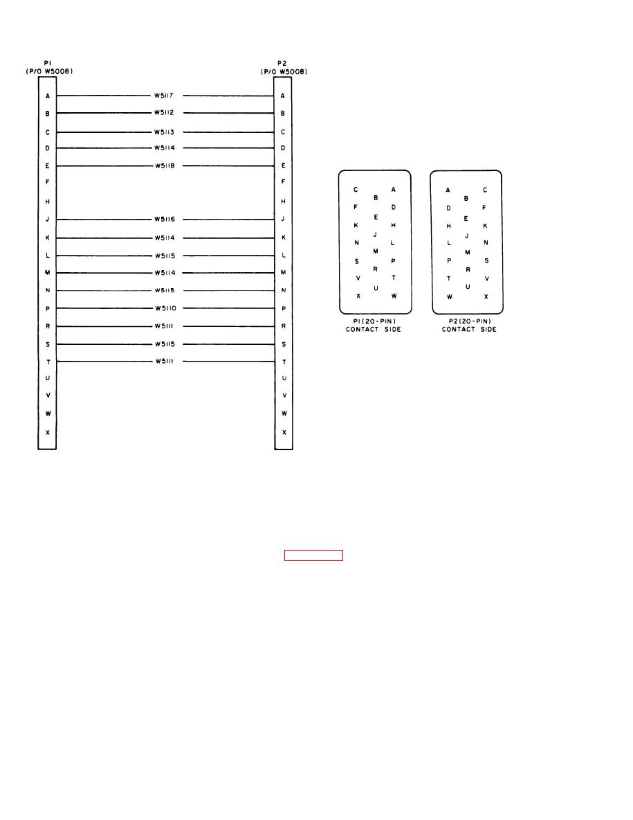
Figure 712. Special Purpose Cable Assembly CX10436/PPPS-5, schematic diagram.
(7) Check cable for correctness, contin-
(2) Make sure that ends of wires are clear
u i t y , and shorts before returning
of surplus solder and are neat and
cable to service.
trim.
(3) F e e d cable end through loosened
c. If repairs require cable replacement, refer
strain clamp and cable opening in
to figure 713 for wire and circuit details.
shell.
(1) Strip end of each wire one-eighth
(4) With plastic sleeves retracted on wire
inch.
leads, insert lead ends through eyes
(2) Insert cable end through shell from
of designated terminals on connector
clamp end.
body, clinching and soldering each
lead as inserted.
(3) Slip 3/8-inch long plastic sleeve over
each wire. Retract to keep stripped
(5) Slip plastic sleeves along wire and
end of wire clear.
over terminals.
(6) Reassemble connector, making cer-
(4) Thread each wire lead through the
eye of the designated terminal on the
tain that strain clamp is tightened.
AGO 7918A
7-12


 Previous Page
