
TM 11-6625-1683-15
(4) Slip replacement plastic insulating
e. Solder contacts of new connector to
grip over red rubber lead.
conductors.
(5) Solder stripped end of red rubber
f. Assemble parts of connector (two halves
lead to replacement pin section.
and a hood) and screw them together.
(6) Screw fitting together.
g. Install new boot by slipping 1 1/2-inch
c. Replace lead as follows:
length of No. 2 shrink sleeving over connec-
(1) Strip insulation one-eighth inch from
tor, and shrink in place by applying heat.
each end of wire.
(2) Solder and assemble as instructed in
7-17. Electrical Lead CX-10449/PPS-5
b(1) through (6) above.
a. Replace six-contact connector as follows:
7-18. Special Purpose Electrical Cable
(1) Unscrew cap section from terminal
Assembly CX-10435/PPS-5
body section.
(2) Unsolder red rubber lead from ter-
a. Male Connector. Replace male connector
minal B.
as follows:
(3) On replacement connector, intercon-
nect terminals A to D and E to F.
(1) Remove epoxy bead that secures plug
to shell.
(4) Solder red rubber lead to terminal B.
(5) Slip cap section over lead and screw
(2) R e m o v e rubber sealing compound
it to terminal body section.
from flange end of shell.
(3) Tap connector to loosen it from shell;
b. Replace single connecting tip as follows:
slide shell back over cable.
(1) Unscrew plastic insulting grip from
(4) Unsolder conductors from connector
tip.
contacts.
(2) Unsolder red rubber lead.
(3) Remove discarded fittings.
(5) On replacement connector, remove
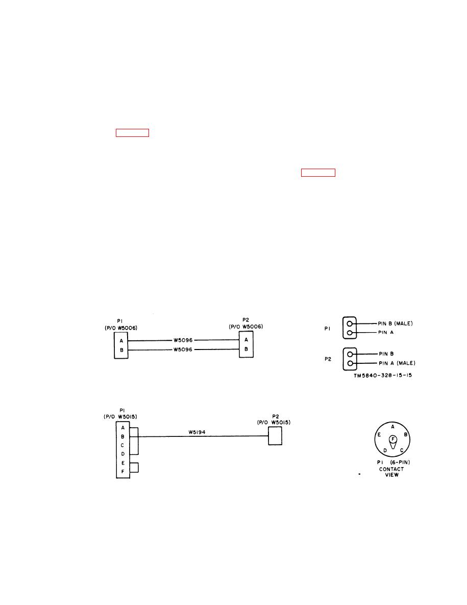
Figure 7-18. Specal purpose Cable Assembly CX-10434/PPS-5, schematic diagram.
TM5840-328-15-29
Figure 7-19. Electrical Lead CX-10449/PPS-5, schematic diagram.
7-17

 Previous Page
