Home
Download PDF
Order CD-ROM
Order in Print
Home
>
Test Facility Manuals and other related material
>
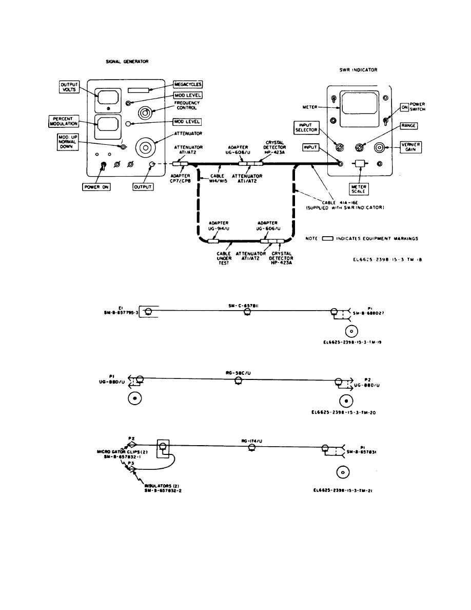
> Figure 6-6. RF cable insertion losses, calibration connections.
Procedure for Cable W39
Figure 6-10. Cable W32, schematic diagram.
TM-11-6625-2398-15-3 Test Facilites Set AN/TPM-24(V)3 (NSN 6625-00-133-7865) Manual
Page Navigation
42
43
44
45
46
47
48
49
50
51
52
TM
11-6625-2398-15-3
Figure
6-6.
RF
cable
insertion
losses,
calibration
connections.
Figure
6-7.
Cable
W13,
schematic
diagram.
Figure
6-8.
Cable
W14/W15,
schematic
diagram.
Figure
6-9.
Cable
W16,
schematic
diagram.
6-17


 Previous Page
