TM 11-6625-928-35
Section Il. REPAIRS
3-6. General Parts Replacement Techniques
a. All parts on the chassis and panel of the
maintenance kit are easily replaced without spe-
cial procedures. Figures 3-1 through 3-10, 5-8
and 5-9 show the location and orientation of
parts on the chassis. Wiring information for re-
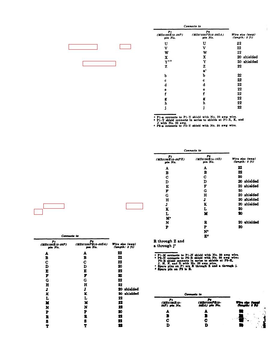
pairing cables given in paragraph 3-7.
b. To prevent damage to components of the
maintenance kit, use a pencil-type soldering iron
with a 25-watt maximum capacity. If the iron
power source is ac power, use an isolating trans-
former between the iron and the line. Do not use
a soldering gun; damaging voltages can be in-
duced in components.
c. The following tools from the MK1191/AR
should be used in the repair of maintenance kit
connectors:
Tool
Use
c. Cable CX-10890/U. Cable CX-10890/U
Adapter, Crimp MS3191-1
Crimps pins or sockets on
cable wires.
(W4) is a 15-wire, rubber-insulated cable with
Tool, Extractor CET 20A
Extracts size 20 pins or
multipin plugs P1 and P2.
sockets from connectors.
Tool, Extractor CET 16
Extracts size 16 pins or
sockets from connectors.
Tool, Insertion CIT 20
Inserts size 20 pins or
sockets in connectors.
Tool, Insertion CIT 16
Inserts size 16 pins or
sockets in connectors.
3-7. Cable Wiring
a. Cable CG-3475/U. Cable CG3475/U (W1)
consists of 6 feet of RG-188A/U. The coaxial
cable is terminated with right-angle female plug
P1 (fig. 3-15) and male BNC plug P2 (fig. 3-
b. Cable CX-10889/U. Cable CX-10889/U
(W2 or W3) is a 32-wire, rubber-insulated cable
terminated with multi-pin plugs P1 and P2.
d. Cable CX-10891/U. Cable CX-10891/U
(W5 or W6) is a 32-wire rubber-insulated cable
with multipin plugs P1 and P2.
3-25
Change 3


 Previous Page
