
TM 11-6625-1683-15
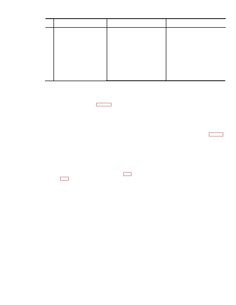
Item
Probable trouble
Trouble symptom
Checks and corrective measures
No.
d. Block 700 power converter de-
d. Replace block 700 power converter.
fective.
Defective connector or defective
3
No voltage output at any one
Replace block 700 power converter.
block 700 power converter.
or all block 700 test jacks.
If not effective, requires higher
category maintenance.
Defective connector or defective
Replace block 2300 power converter.
4
No voltage output at any or all
component block 2300 power
block 2300 test jacks.
If not effective, requires higher
category maintenance.
converter.
Indicator lamp in block 1200
5
Defective
lamp
------------------
Replace defective lamp: DLY (DS
5003), LV (DS5006), DRIVE
does not light during relay
(DS5004), FWD REV (DS5005).
control circuit board test.
(4) Rotate the screws in a clockwise di-
4-14. Repairs and Adjustments
rection, alternately taking up a few
a. Replacement of Indicator Lights.
turns on one and then the other.
( 1 ) G r a s p the knurled ring around the
Tighten until snug, but do not force.
base of the lens (fig. 41) with the
c. Replacement of Block 2300 Power Con-
fingers, and remove the combined
verter.
lamp and lens by rotating it counter-
clockwise. Remove the combined lamp
( 1 ) U n s c r e w the four retaining screws
and lens.
b y turning them counterclockwise.
( 2 ) Replace the lamp and lens combina-
Each one is located in a corner of the
tion, screwing the unit in a clockwise
power converter face panel (fig. 41).
direction until finger tight.
Remove the screws.
b. Replacement of Block 700 Power Con-
( 2 ) Gently lift out the power converter.
verter.
( 3 ) M a n u a l l y separate the two sections
(1) By turning them counterclockwise,
of the connector in back of the power
u n s c r e w the two captive retaining
converter. This completes detachment.
s c r e w s located, respectively, in the
( 4 ) M a n u a l l y interconnect the replace-
upper right and lower left corners of
ment power converter connector with
the power converter face panel (fig.
the mating plug.
( 5 ) Set the power converter into the test
internal connector assembly.
panel with all mounting holes in
(2) Gently lift out the power converter.
proper alignment.
(3) Carefully set the replacement power
( 6 ) R e i n s e r t the retaining screws, and
converter into the test panel, position-
tighten in a clockwise direction. Do
ing it to permit engagement of the
not force.
retaining screws.
4-5

 Previous Page
