
C 3, TM 11-6625-1683-15
n. The positive side of the dc output is
circuit. The circuit breaker is closed by press-
ing and releasing the panel button.
grounded. The -6-volt dc output is brought to
INPUT POWER switch S1-C for distribution
d. RCVR-XMTR switch breaker CB4, rated
to the various circuits requiring this potential.
at 12 amperes, is a two-pole device. One pole,
bridging terminals 3 and 4, is in the main -6-
volt supply line, when the equipment is in the
6 VDC operating mode. Any current demand in
excess of 12 amperes will activate the circuit
breaker, thereby opening the entire -6-volt cir-
cuit. The second pole, bridging terminals 1 and
2, is in the ground return circuit of the re-
ceiver-transmitter power converter (block
700). Any excessive current demand by the
converter unit will cause the 6-volt supply cir-
cuit to open. Both poles of the circuit breaker
are closed simultaneously by setting it to ON.
5-6. REMOTE CABLE Test Circuit
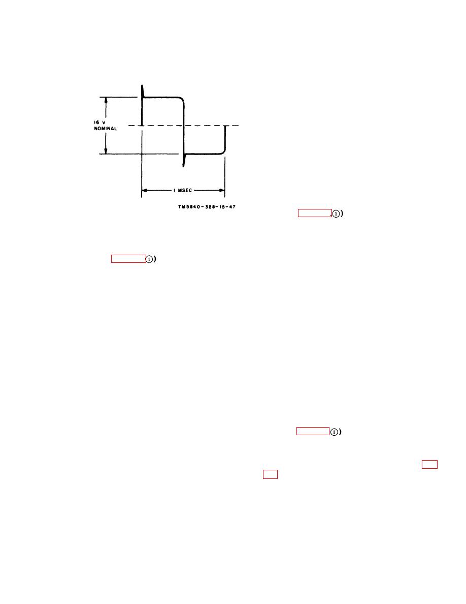
Figure 5-1. Waveshape of ouput at secondary
a. The REMOTE CABLE test circuit tests
terminals 8 and 10 of transformer T1.
the remote cable (Special Purpose Electrical
Cable Assembly CX-20004/PPS-5 in the AN/
5-5. CIRCUIT BREAKERS
PPS-5) of the rader set by connecting the con-
ductors of the cable in series and measuring
Four magnetically actuated circuit breakers
the voltage output at one end of the series-
are employed to guard against overload dam-
connected conductors while applying -6 volts
age to the equipment.
at the other end. A conductor that is broken
(open) will cause a 0-volt reading; conductors
a. MAIN PWR push breaker CB1, rated
shorted to each other will cause a voltage read-
at 1.5 amperes, is in one side of the 115 VAC
ing higher than -2.0 0.5 volts; and a high
power input circuit. Any current demand ex-
resistance in a conductor will cause a voltage
ceeding this rating will cause the magnetic
reading lower than 2.0 0.5 volts.
actuator to trip the switch, opening the power
b. At pin W of connector J18, -6 volts is ap-
line circuit. The circuit breaker is closed by
plied, and, at pin r of connector J19, TEST
pressing and releasing the panel button.
jack TP26 provides a means of measuring the
b. CONTROL push breaker CB2, rated at 3
voltage output. Resistor R63 provides a shunt
amperes, is in the 6-volt supply to block 2800,
resistance load from TEST jack TP26 to
block 900, block 1000, and the drive motor test
ground.
circuits. Current in excess of the circuit break-
er rating will cause the breaker to trip, thereby
5-7. TRIG Output Circuit
opening the -6-volt dc supply circuit. The cir-
cuit breaker is closed by pressing and releasing
the panel button.
a. TRIG output test jack TP50 and TP51
c. CONT-IND push breaker CB3, rated at 3
derive a test trigger pulse from networks Zl,
amperes, is in the -6-volt supply to the control-
22, and 23. The modulator trigger pulse (fig.
indicator power converter (block 2300). A rise
in current beyond its 3-ampere rating will
transmitter power converter is shaped by net-
work Z1 into a waveform with a steep leading
cause the circuit breaker to trip and open the
5-3

 Previous Page
