
TM 11-6625-1683-15
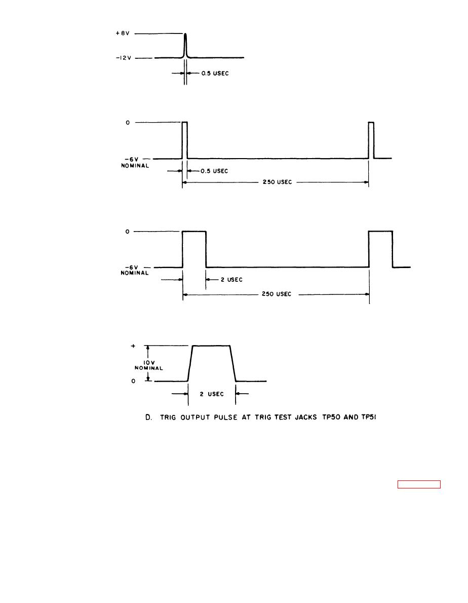
A. INPUT PULSE AT PIN 4 0F SQUARING AMPLIFIER 21
B. OUTPUT AT PIN 8 OF SQUARING AMPLIFIER 22
INPUT AT PIN 4 OF ONE-SHOT MULTIVIBRATOR 22
C. OUTPUT AT PIN 7 OF ONE -SHOT MULTIVIBRATOR 22
INPUT AT PlN 2 OF DRIVER AMPLIFIER 23
TM5840-328-15-49
Figure 5-3. Waveforms in trigger shaping circuits.
likewise, between Q2 and Q4 in the other am-
system to adequately pass the rectangular
plifier series to insure the necessary low fre-
wave coupled into it from the one-shot multi-
quency response. The appearance of the out-
vibrator. Direct coupling is employed between
put waveshape is indicated in D, figure 5-3.
Q1 and Q3 in the one amplifier series and,
5-5
AGO 7918A

 Previous Page
