TM 11-6625-1683-15
d. Set the 100 block power switch to O F F .
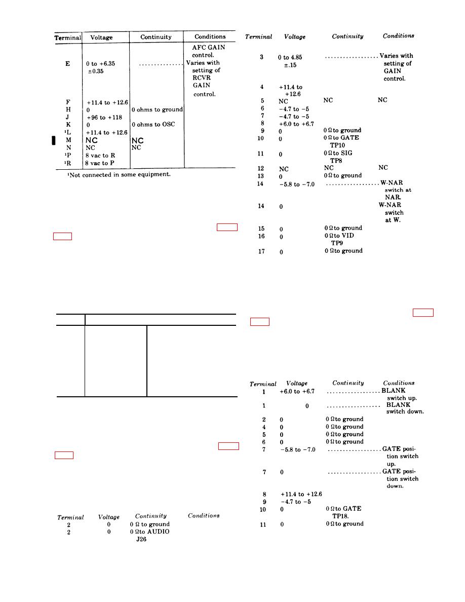
8.1-8. Block 300 Voltage and Continuity
Test
a. C o n n e c t t h e e q u i p m e n t a s r e q u i r e d ( p a r a
b. Set the 300 block power switch to ON. Check
the 300 connector J4, RCVR-XMTR VIDEO test
jack TP2, and CONT-IND VIDEO test jack TP3 as
d. Set the 400 block power ON-OFF switch to
indicated in c below; use the CX-10429/PPS-5 cable
OFF.
(or CX-10444A/PPS-5).
c. M a k e v o l t a g e a n d / o r c o n t i n u i t y m e a s -
8.1-10. Block 500 Voltage and Continuity
Tests
urements as indicated in the chart below.
a. Connect the equipment as required (para
Voltage
Continuity
Terminal
I
o
b. Set the 500 block power ON-OFF switch to ON.
0 ohms to ground
A
+6.0 to +6.7
B
Check the 500 connector J8 and GATE test jack
4.7 to 5.0
c
TP18 as indicated in c below; use the CX-1044W
0 ohms to RCVR-
o
D
PPS-5 cable.
XMTR VIDEO TP3
c. M a k e v o l t a g e a n d / o r c o n t i n u i t y m e a s -
0
0 ohms to CONT-
E
urements as indicated in the chart below.
IND VIDEO TP3.
0
0 ohms to ground
F
+ 11.4 to +12.6
H
d. Set the 300 block power ON-OFF switch to
OFF.
8.1-9. Block 400 Voltage and Continuity
a. C o n n e c t t h e e q u i p m e n t a s r e q u i r e d ( p a r a
b. Set the 400 block power ON-OFF switch to ON.
Check 400 connector J6, and AUDIO jack J26 as
indicated in c below; use the CX-10444/PPS-5 cable.
c. Make voltage and/or continuity meas-
urements as indicated in the chart below.
d. Set 500 block power ON-OFF switch to OFF.
CHANGE II 8.1-3


 Previous Page
