
TM
11-6625-1683-15
8.1-17. Block 2200 Voltage and
3
Continuity Tests
4
Connect the equipment as required (para
a.
5
6
b. Set the 2 2 0 b l o c k p o w e r O N - O F F '
switch to ON. Check both 2200 connectors
7
(J22 and J23) and the test jacks. (MARK
8
TP46, VID B TP49, VID RGF TP45, VID
9
SEL TP37, VID IN TP44, SWP TP47, SWP
10
TP48, BLANK TP36, ASTIG TP27, B VID
T P 3 9 , MTI TP38, MTI TP40, MTI TP41,
11
MTI TP43, MTI TP42) (c and d below), use
the CX-10442/PPS-5 cable.
11
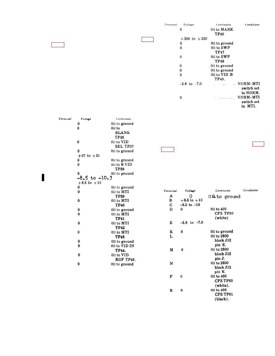
c. Make voltage and/or continuity measure-
ments for connector J22 as indicated in the
chart below.
e. Set the 2100 block power ON-OFF switch
to OFF.
1
3
8.1-18. Block 2400 Voltage and
Continuity Tests
4
5
b. Set the 2 4 0 0 b l o c k p o w e r O N - O F F
6
7
switch to ON, Check 2400 connectors Jll as
8
indicated in c below; use the CX-10436/PPS-
5 cable.
9
10
c. Make voltage and/or continuity measure-
11
ments as indicated in the chart below.
12
13
14
16
16
17
18
19
20
21
22
d. Make voltage and/or continuity meas-
urements for connector J23 as indicated in the
chart below.
CHANGE II 8.1-7

 Previous Page
