
C6,
TM
11-6625-1683-15
(a) Perform a continuity test between
each pin of P1 and the correspond-
ments as indicated in the chart below.
i n g pin; use the RX1 range on
Multimeter ME-26(*)/U, The re-
sistance should be less than 0 . 1
ohm,
(b) P e r f o r m a leakage and high-pot
test from each pin of P1 to all
other pins of P1 and to each con-
nector hood. Leakage should be
greater than 10 megohms. High-
pot at 500 volts ac for 1 minute.
(2) CX-10480 PPS-5 cable assembly
(block 800).
(a) Perform a continuity test between
8.1-25. REMOTE CABLE Test
each pin of P1 and the correspond-
ing pin of P2; use the RX1 range
o n Multimeter ME-26(*)/U. The
resistance should be less than 0.1
ohm.
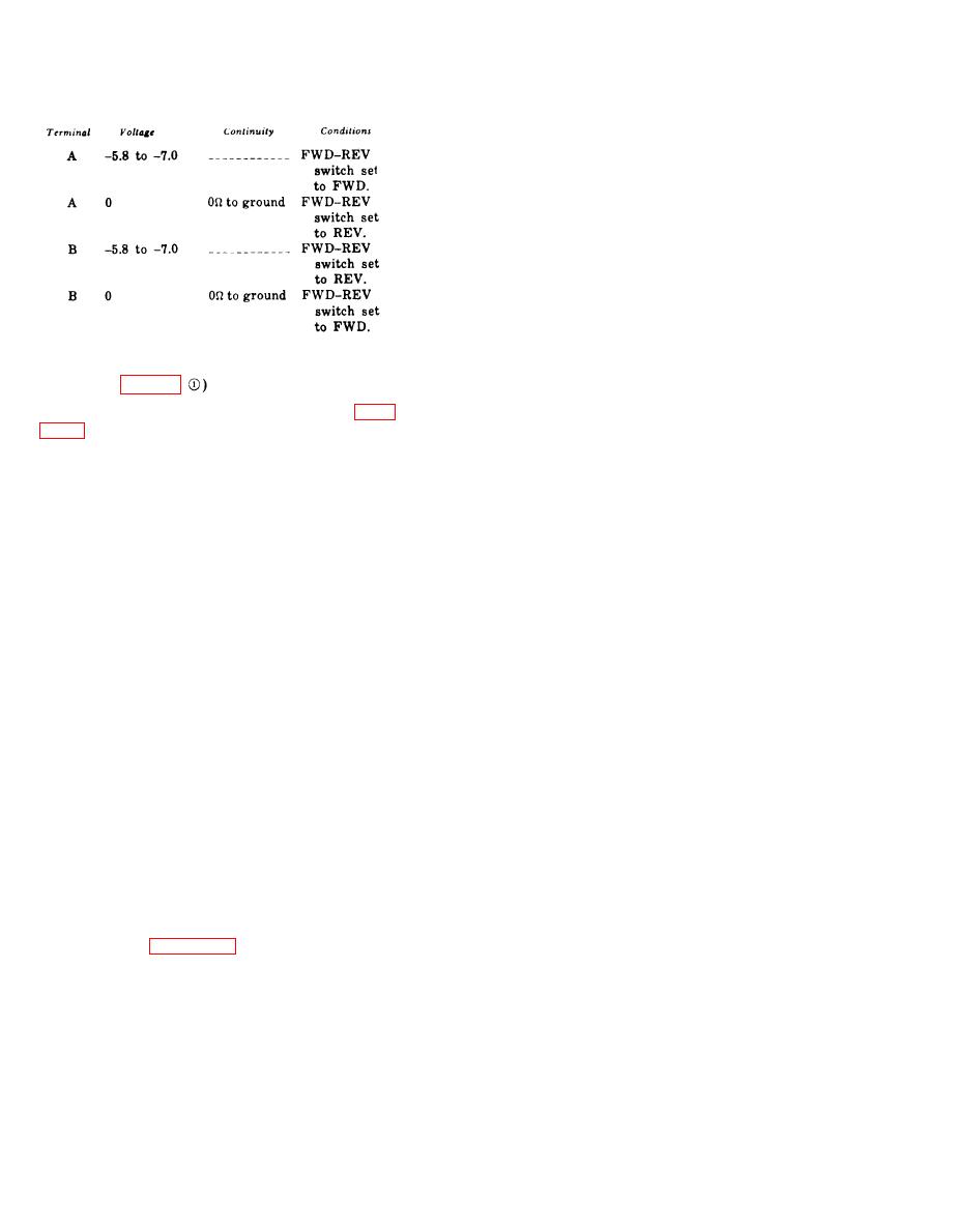
b. Measure the voltage at connector J18
(b) P e r f o r m a leakage and high-pot
pin W, the voltage should be -6 .06 volts.
test from each pin of P1 to all
other pins of P1 and to each con-
c. For connector J18, there should be zero
nector hood. Leakage should be
ohms between pins V and U, T and S, R and
greater than 10 megohms. High-
P, N and M, L and K, J and H, G and F,
pot at 500 volts ac for 1 minute.
E and D, A and X, j and g, h and f, e and d,
(3) CX-10441 P P S - 5 cable assembly
c and b, a and Z, Y and i, q and p, n and m,
(block 2100).
k and r.
(a) Perform a continuity test between
d. For connector J-19, there should be zero
each pin of P1 and corresponding
ohms between pins W-V, U-T, S-R, P-N, M-L,
pin of P3 and between each pin
KJ, H-G, FE, DA, Xj, g-h, f-e, d-c, b-a,
of P2 to the corresponding pin of
Z-Y, i-q, p-n, m-k, and r-TEST (WHT) TP26.
P4. Use the RX1 range on Multi-
meter ME-26(*)/U.
e. There should be 56 ohms 5 percent be-
tween TEST (WHT) TP26 and ground.
(b) P e r f o r m a leakage and high-pot
test from each pin of P1 and P2
to all other pins of both P1 and
8.1-26. Special Purpose Cable
P2 and to each connector assembly
Assemblies Tests
frame. Leakage should be greater
a. General. The following test procedures
than 10 megohms. High-pot at 500
should be performed in the order listed. Ap-
volts ac for 1 minute.
plicable standards are indicated for each item.
(4) C X - 1 0 4 4 2 P P S - 5 cable a s s e m b l y
b. Test Equipment Required, M u l t i m e t e r
(block 2200).
ME-26 (*), U and Test Set, Insulation Break-
(a) Perform a continuity test between
down AN/GSM6 are the equipment required
each pin of P1 and the correspond-
for this test (para 8.1-3).
ing pin of P3, and between each
pin of P2 and the corresponding
c. General Procedures and Requirements.
(1) CX-10429 PPS-5 cable assembly
pin of P4. Use the RX1 range on
Multimeter ME26(*)/U. The re-
(block 300).
8.1-1O

 Previous Page
