
TM 11-6625-1683-15
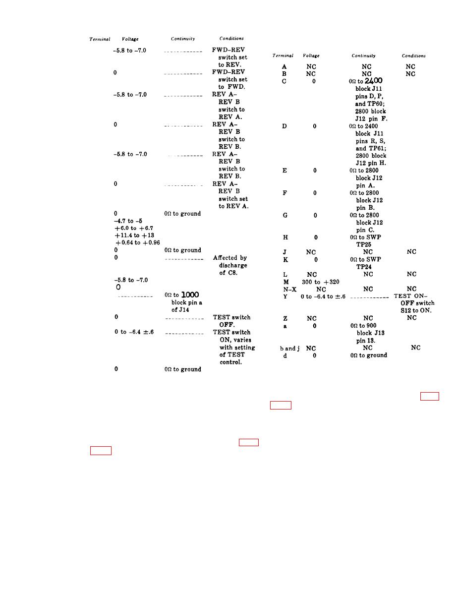
c. Make voltage and for continuity measure-
ments as indicated in the chart below.
1
1
2
2
3
3
4
5
6
7
8
9
10
11
12
13
14
14
15
8.1-15. Block 1200 Voltage and
Continuity Tests
d. Set the 900 power ON-OFF switch to
OFF.
b. Set the 1200 block power ON-OFF switch
8.1-14. Block 1000 Voltage and
to ON. Check 1200 connector J9, DLY indicator
Continuity Tests
light DS3, FWD-REV indicator light DS5,
DRIVE indicator light DS4, and LV indicator
light DS6 as indicated in c below; use the
CX-10433/PPS-5 cable.
b. Check 1000 connector J14 and SW P test
jacks TP24 and TP25 as indicated in c below;
use the CX-10435/PPS-5 cable.
ments as indicated in the chart below.
CHANGE II 8.1-5

 Previous Page
