
TM 11-6625-1683-15
Voltage
Terminal
Continuity
Conditions
Warning
10
-1,450 to
De voltage
Voltage up to 2,000 volts is present
obtained
-1,900
between
at connector J16 and the test cable
pin 10 and
assembly when the CRT TEST push-
ground,
button is depressed.
with CRT
TEST push-
button
Caution
depressed.
11
CRT TEST
-1,200 100
Under no conditions should the CRT
pushbutton
TEST pushbutton be depressed when
depressed
measuring the filament voltage. Dam-
and A
FOCUS
age to the multimeter will result.
R51
adjusted.
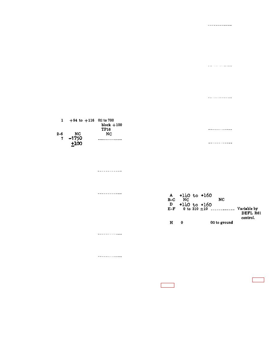
c. Make continuity and/or voltage measure-
CRT TEST
1,680 100
12
ments as indicated in the chart below.
pushbutton
depressed
and B
Terminal
Continuity
Conditions
Voltage
BRIGHT
R46
adjusted,
+ 1,800 to
CRT TEST
13
pushbutton
+2,300
depressed.
CRT TEST
-1,200 100
CRT TEST
14
pushbutton
pushbutton
depressed
depressed
and B
and B
BRIGHT
FOCUS
R49
R48
adjusted.
adjusted.
8 and 10 1.35 to 1.65
Ac voltage
d. Make voltage and/or continuity measure-
obtained
between
ments for connector J17 as indicated
the
in
pins 8 and
chart below.
10.
Continuity
Conditions
Terminal
Voltage
8
-1,450 to
Dc voltage
-1,900
obtained
between pin
8 and
ground.
with CRT
TEST push-
button de.
pressed.
8.1-23. Block 600 LOAD Tests
9 and 15 1.35 to 1.65
Ac voltage
obtained
The resistance between LOAD test jack J27
between
to ground should be 2,020 ohms 5 percent.
pins 9 and
T h e resistance between LOAD (BLU) test
16.
9
-1,500 to
point TP19 and ground should be 10 ohms
Dc voltage
-
-1,900
obtained
5 percent.
between pin
9 and
8.1-24. Drive Motor B1 001
ground,
with CRT
TEST push-
button
b. Check motor power connector J15 (c be-
depressed.
low) ; use the CX-10434/PPS-5 cable.
CHANGE II 8.1-9

 Previous Page
