TM 11-6625-1696-12
position of the power tubes in the cavities. Three test
the Accessory Kit, Test MK-1985(V) l/GRM-95(V)2. Air
points J3, J4 and J5, located on the base of the test
is supplied to the test fixture from the transmitter test
fixture, are provided to allow resistance measurements
facility. When an assembly is mounted on the test
of the thermistor mounted on the tubes in the AUT. The
fixture and the correct air pressure is being supplied, the
direct drive tuning mechanism is controlled by the
contacts of the pressure differential switch will close and
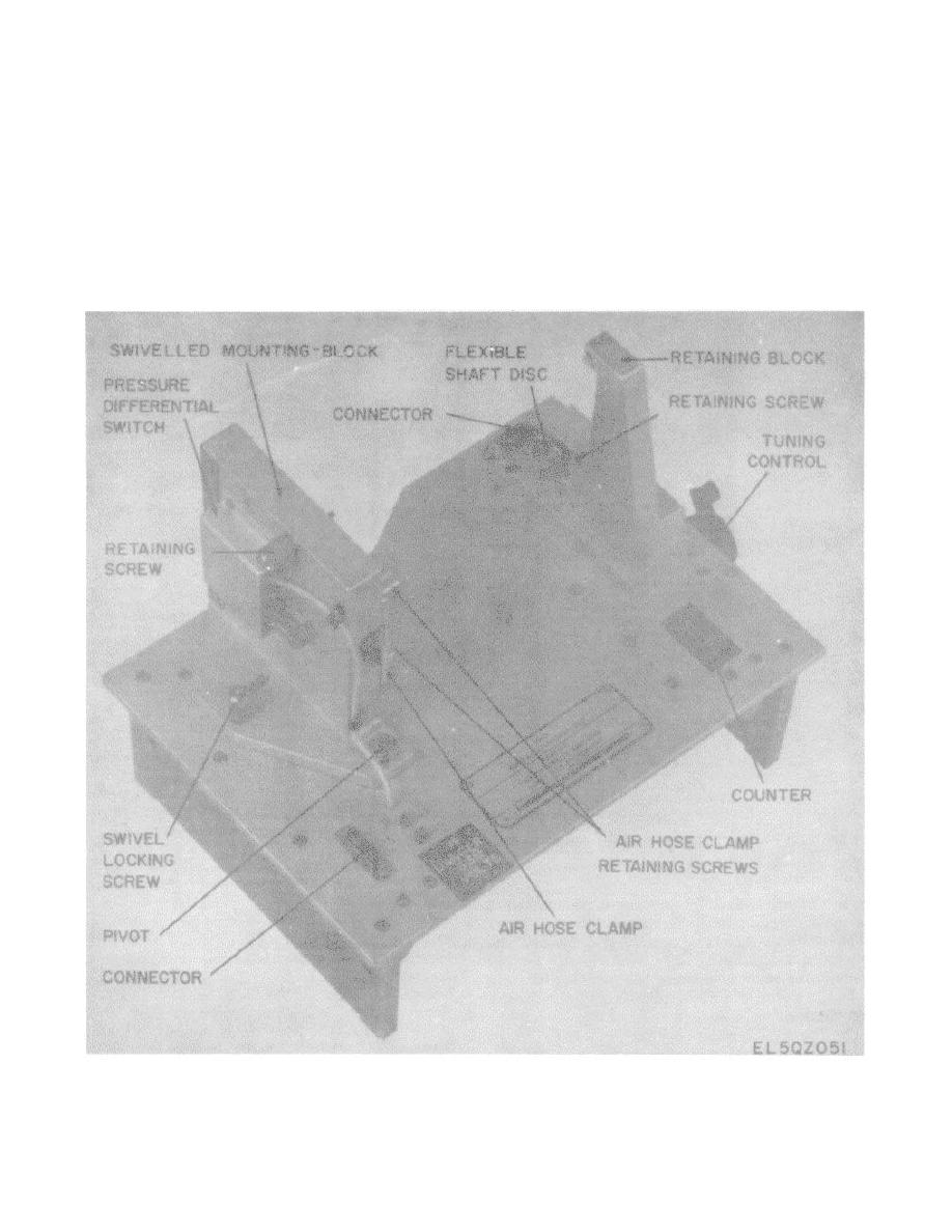
control knob which also drives the counter. The counter
complete a 600 volt interlock circuit through connector
operates in the range from 0.8 to 60.4 MHz and locks at
J1 pins 8 and 9. Closing the interlock circuit permits the
both ends. The counter is calibrated in increments of
600 volt supply in the transmitter test facility to be
0.02 MHz so that the RF amplifier can be checked at
switched on and fed to the output tubes of the AUT.
c. Two holes (V1 and V2) are provided in the
any designated point.
swiveled mounting block to facilitate adjustment of the
Figure 3-12. Radio Frequency Amplifier Test Fixture TS-3827/GRM-95(V)2.
3-32


 Previous Page
