
TM 11-6625-1696-12
3-57. Test Fixture, Frequency Multiplier TS-
transmitter test facility. The tuning mechanism drive
3829/GRM-95(V)2 (fig. 3-13)
locks at the counter setting of 000 and 220 to prevent
overdrive. Frequency multiplier 39A3 (245-800487-000)
The transmitter frequency multiplier 40A2 (245-800491-
is similarly mounted on the test fixture except that this
000) is mounted on the same side of the test fixture as
unit is mounted on the opposite side of the gear
the counter. When the AUT is mounted on the test
assembly to that of the counter. When mounted, the
fixture, the plug of the AUT is automatically engaged
receiver frequency multiplier 39A3 automatically
with J1 of the test fixture. J1 is parallel wired to J2
engages J4 which is parallel wired to J3, through which
through which operating voltages to the AUT are
operating voltages are supplied to the 39A3 assembly
supplied. J2 is connected to the test facility by a special
under test.
purpose cable 2W5 (457-573). This cable assembly is
located
in
the
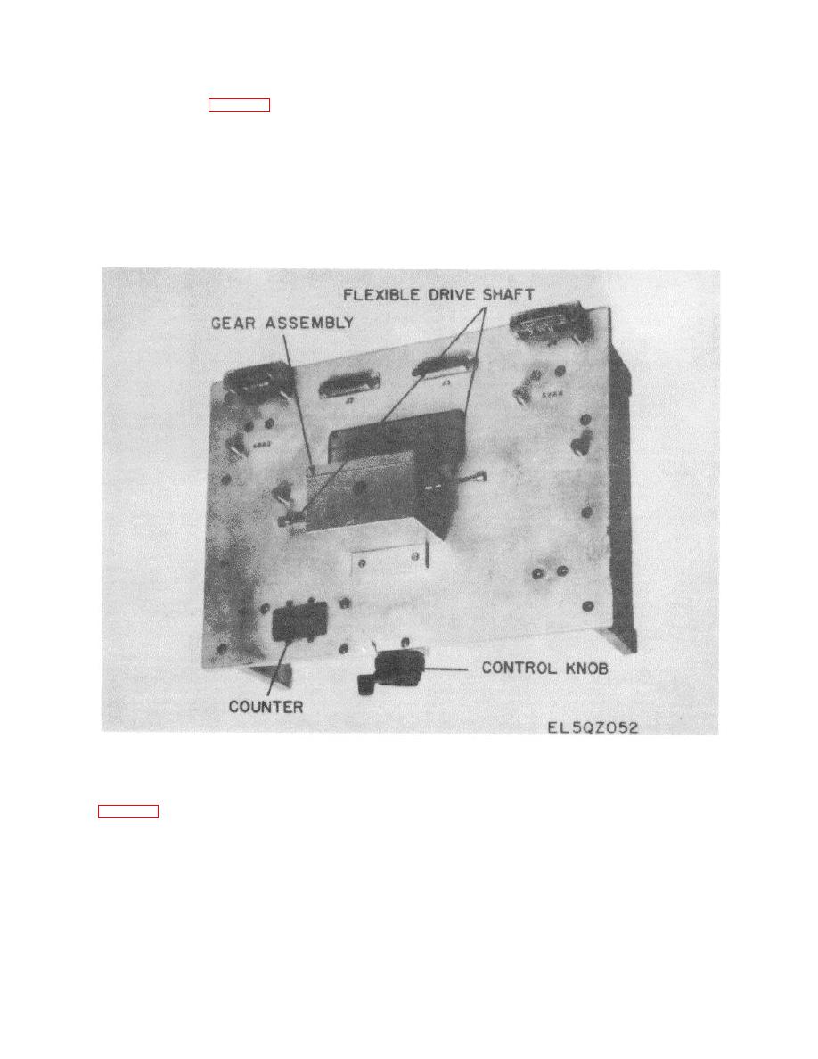
Figure 3-13. Radio Frequency Amplifier Test Fixture TS-3827/GRM-95(V)2.
3-58. Test Fixture, Bandpass filter TS-3830/GRM-
This unit engages the bevel gear on the opposite side of
95(V)2 (fig. 3-14)
the test fixture. The AUT is held in position by retaining
screws located under the baseplate of the test fixture.
The test fixture is used to test bandpass filters 39FL1,
The tuning mechanism drive locks at the counter
39FL2, and 40FL1. These filters are mounted vertically
settings of 000 and 0985 by locking washers on the
and engage the drive shaft and disk on one side of the
main drive shaft. One turn of the control knob produces
test fixture. The same test fixture is used to test
approximately three turns of the drive shaft.
bandpass filter 39FL3 which is also mounted vertically.
3-33

 Previous Page
