
TM 11-6625-2398-15-2
(8) Hairpin the black wire and insert between
outer ground ring and cable braid.
(9) Using crimping tool, crimp outer ground
ring, black wire and inner ground ring.
(10) Except for black wire, strip 3/16 inch of
insulation from the end of each wire in the assembly (fig.
(11) Cover inside edge of backshell with
electrical tape (fig. 7-32).
(12) Solder other end of ground wire connected
in step (8) above to backshell.
(13) Slide backshell onto cable assembly.
(14) Using crimping tool, pin wire ends and
insert pinned wires into connector (fig. 6-30).
(15) Assemble backshell to connector using
nuts, screws, and lockwashers supplied.
(16) Slide 1 -inch sleeving past ground ring
and butt up against ground ring (fig. 7-33).
(17) Using heat gun, shrink the sleeving.
(18) Sequentially repeat steps (16) and (17)
above for the 2 1/4-inch sleeving, then 2 3/4-inch
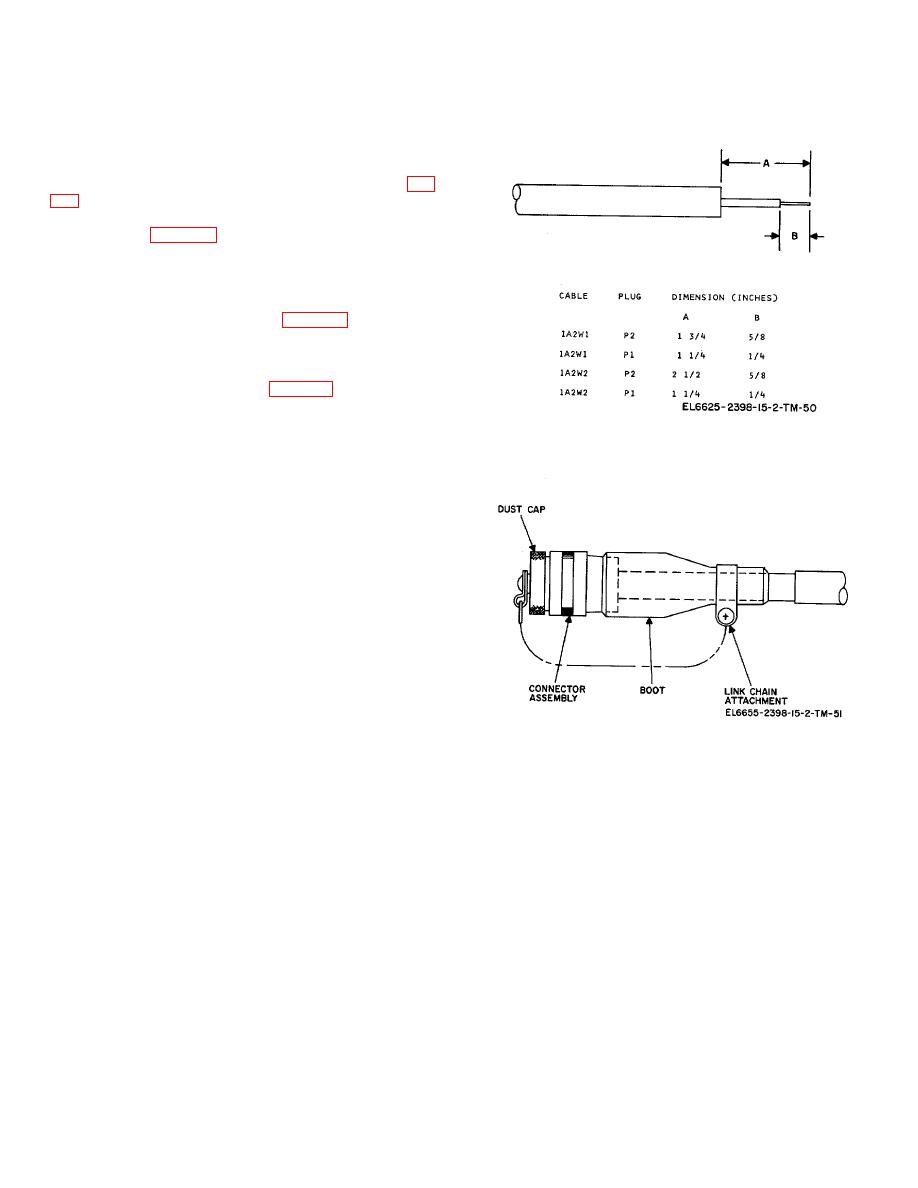
Figure 7-3. Stripping detail, cable IA2 WI/ W2.
sleeving. Align these pieces with front edge of first
piece. Apply R.T.V. adhesive under last piece of
sleeving prior to shrinking.
(19) Clean end of cable and apply thermofit
adhesive to area which will be covered by cable boot.
(20) Using heat gun, shrink boot and tag
marker.
(21) Remove excess adhesive from boot and
sleeving.
(22) Attach dust cover to cable, with cable
clamp.
NOTE
Align the 2 1/4-and 2 3/4-inch piece of
sleeving with the front edge of the 1
1/4-inch piece of sleeving. Before
shrinking the 2 3/4 inch piece of
sleeving, coat rear area of sleeving
Figure 7-4. Typical cable/connector arrangement.
with R.T.V. adhesive.
7-21

 Previous Page
