
TM 11-6625-928-35
(17) Carbon composition resistor, 510 ohms,
3-14. Radio Test Circuit Tests
5 percent, 1/2 watt.
a. Test Equipment and Materials.
(1) Electronic Voltmeter AN/URM-145.
(18) Carbon composition resistor, 82 ohms, 5
percent, 1/2 watt.
(2) Multimeter ME-26B/U.
(3) Multimeter TS-352B/U.
(19) Carbon composition resistor, 68 ohms,
(4) Standing Wave Ratio Indicator IM-
5 percent, 1/2 watt.
157/U.
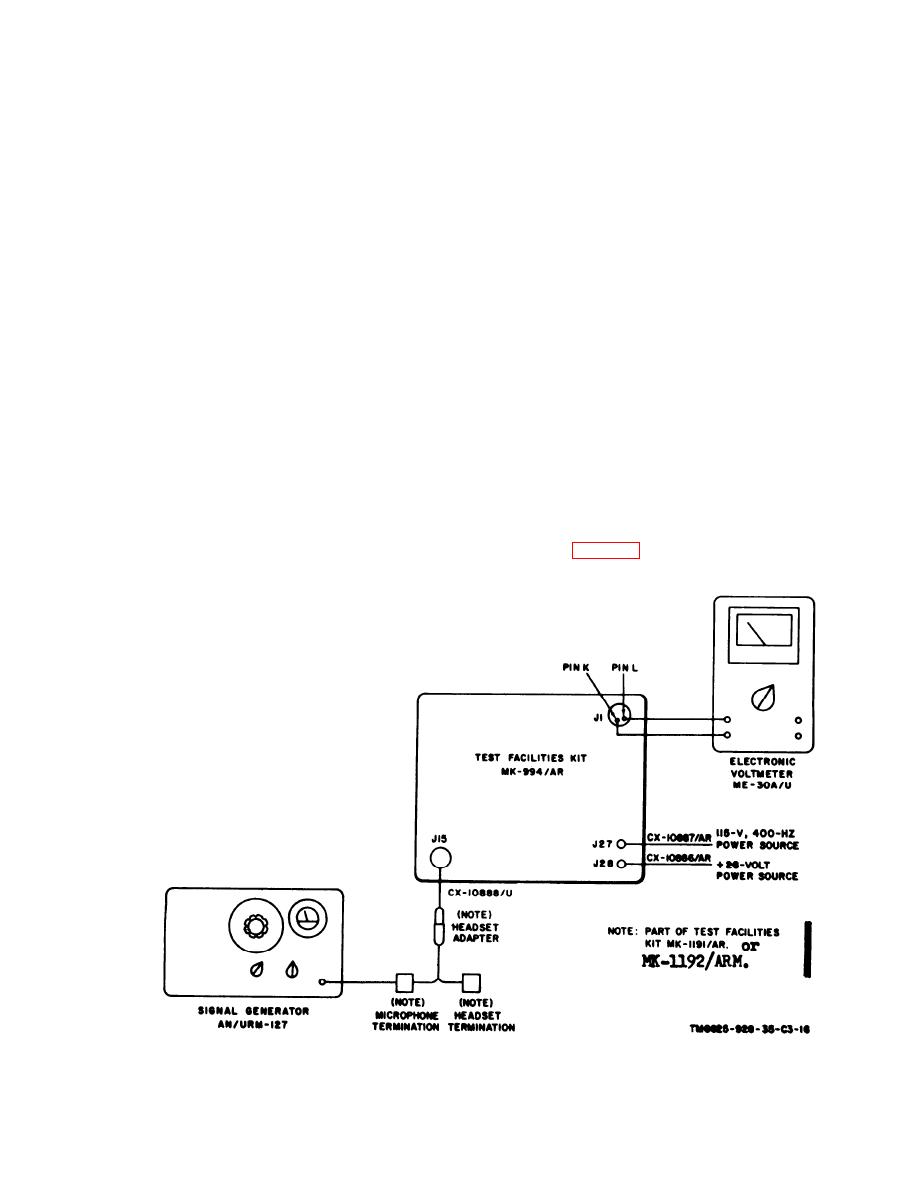
b. Test Connections and Conditions. Tests re-
(5) Detector DT-307/G.
quire that maintenance kit connector P1 be dis-
(6) Electronic Voltmeter ME-30A/U.
connected in certain steps requiring the f rent
(7) Signal Generator AN/USM-44A.
panel and the chassis assembly to be removed
(8) Signal Generator AN/URM-127.
from the bottom case. For ease of testing, it is
(9) Electronic Voltmeter AN/USM98.
advisable to have the front panel and the chas-
(10) Attenuator CN-796( )/U.
sis assembly inserted in the bottom case, but not
secured to the case, so that these assemblies may
(11) 50-ohm BNC adapter from Electronic
be easily removed from the case when required.
Voltmeter AN/URM-145. -
When tests require the connation of the GS ac-
(12) Impedance Adapter MX-1487/URM-
cessories kit microphone and headset termina-
25D.
tions to the headset adapter, connect the red dou-
(13) Headset adapter from GS accessories kit.
ble banana plug from the headset adapter to the
(14) Headset termination from GS accessories
microphone termination and the black double
kit.
banana plug to the headset termination. POW-
(15) Microphone termination from GS
ER connector J28 should be connected to the fa-
accessories kit.
cility +28-volt power source with cable CX-
(16) Carbon composition resistor, 8,200
10886/AR to provide the necessary operating dc
ohms, 5 percent, 1/2 watt.
voltage (fig. 3-18).
Figure 3-18. Typical test setup.
3-29
Change 4

 Previous Page
