
TM 11-6625-1683-15
J1l-P. This termination is monitored at 400
5-22. Block 2300 Control-Indicator Power
C P S test jack TP60 (white). The 4 0 0 - H z
Converter Test Circuit
power is also brought into the test circuit
t h r o u g h paralleled pins J1lR and J1l-S.
a. The power converter (marked PWR.
This input is monitored at 400 CPS test jack
CONV. REMOTE) is removable from the test
TP61 (black).
panel and is identical with the corresponding
unit in the radar set control-indicator. Refer
524. Block 2700 Range Gated Filter
to the technical manual for the radar set for
Assembly Test Circuit
a detailed description and presentation of the
functioning of this unit.
a. Connector J24 provides a means of cir-
b. All dc outputs except the 2,000 volts
cuit and power connection to the radar set
and the + 2,000 volts are brought to test jacks
range gated filter assemblies. ON/OFF switch
located on the test panel adjacent to the power
S27 is a two-pole, two-position toggle switch.
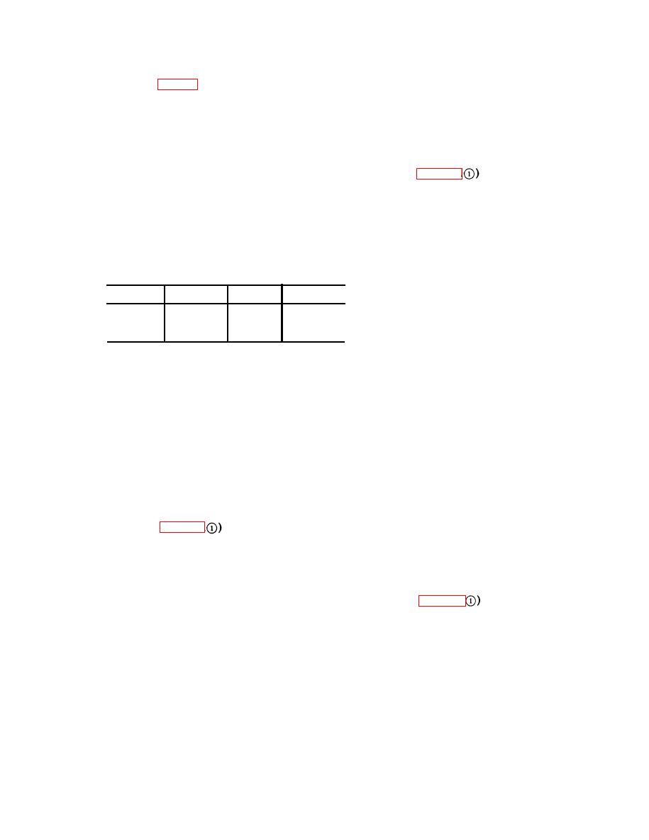
converter. The voltage levels at these moni-
In the ON position, +12 volts is connected to
toring points and the corresponding test jacks
pin J24K, and 12 volts is connected to pin
are as follows:
J24J. In the OFF position, the poles are
connected to dummy load resistors R45 and
Tent point
Volts
Test jack
Volts
R44.
TP57
12
TP58
+35
b. A voltage regulating circuit (consisting
TP59
GND
+12
TP56
of Zener diodes CR9 and CR10, resistors R80
and R81, and capacitors C13 and C14) is con-
c. The 2,000 volts and the +2,000 volts
nected to the 12-volt dc source. The + 3.9-
a r e connected directly to the CRT TEST
volt regulated output is fed to pin J24B,
push-and-hold switch S17 located at the upper
while the 3.9-volt regulated output connects
right corner of the test panel adjacent to the
to pin J24-A.
power converter. Dc power from switch break-
c. The triggering signal generated by shap-
er CB4 is connected to the converter through
ing circuits Zl, Z2, and Z3 is brought to pin
push breaker CB3 and resistor R82. This re-
J24H and, simultaneously, appears at TRIG
sistor simulates the normal voltage drop en-
test jacks TP50 and TP51. VIDEO test jack
countered in the radar set, in the remote 50-
TP53 (green) permits injecting a test input
foot cable, and in the control-indicator circuits.
video signal and connects to pin J24E. VI-
DEO test jack TP54 (blue) permits monitor-
5-23. Block 2400 Azimuth Servoamplifier
ing the output video signal and connects to
Test Circuit
pin J24-L. TRIG test jack TP52 permits mon-
itoring the trigger output signal and connects
to pin J24C.
a. Connector J11 provides a means of cir-
cuit and power connection to the radar set
5-25. Block 2800 Azimuth Counter Test
servoamplifier assembly. ON/OFF switch S14
Circuit
is a two-pole, two-position toggle switch. In
the ON position, 12 volts is connected to
pin J1lC and +12 volts is fed to pin J1lB.
Connector J12 provides interconnection be-
In the OFF position, the poles are connected
tween the block 2800 azimuth counter assem-
to dummy load resistors R37 and R38.
bly, the block 1000 antenna drive unit, and
the block 2400 servoamplifier. Interconnection
b. The 400-Hz power generated in the ser-
of these three units is essential for tests of
voamplifier circuit is brought to the test cir-
the azimuth counter assembly.
cuit through paralleled pins J11-D and
5-13
AGO 7918A

 Previous Page
