TM 11-6625-1696-12
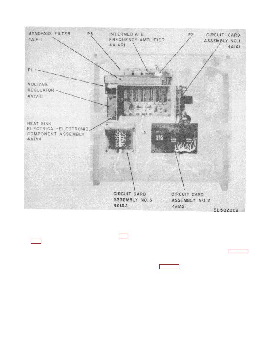
Figure 5-16. RF Modules Test Facility Front Panel, Rear View.
5-28.
Replacement of Heat Sink, Electrical-
and tighten the screws.
e. Connect the heat sink assembly plug with
Electronic Component Assembly 4A1A4 (fig.
its mating connector and tighten the two captive screws.
f Replace the front panel in the case. 5-29.
a. Remove the RF modules test facility front
Replacement of Voltage Regulator 4AlVR1 (fig. 5-16)
panel from the case, and lay the panel face down-
wards.
5-29.
Replacement of Voltage Regulator 4A1VR1
b. Loosen the two captive screws in the heat
sink electrical-electronic component assembly (heat sink
a.
Remove the RF modules test facility front
assembly) plug, and disconnect the plug.
c. Loosen the five captive screws that secure
panel from the case, and lay the panel face down-
wards.
the heat sink assembly to the front panel and remove
the heat sink assembly.
d. Aline the five captive screws of the
replacement heat sink assembly with the mounting posts
5-21


 Previous Page
