
TM 11-6625-1696-12
b. Loosen the captive screw that secures the
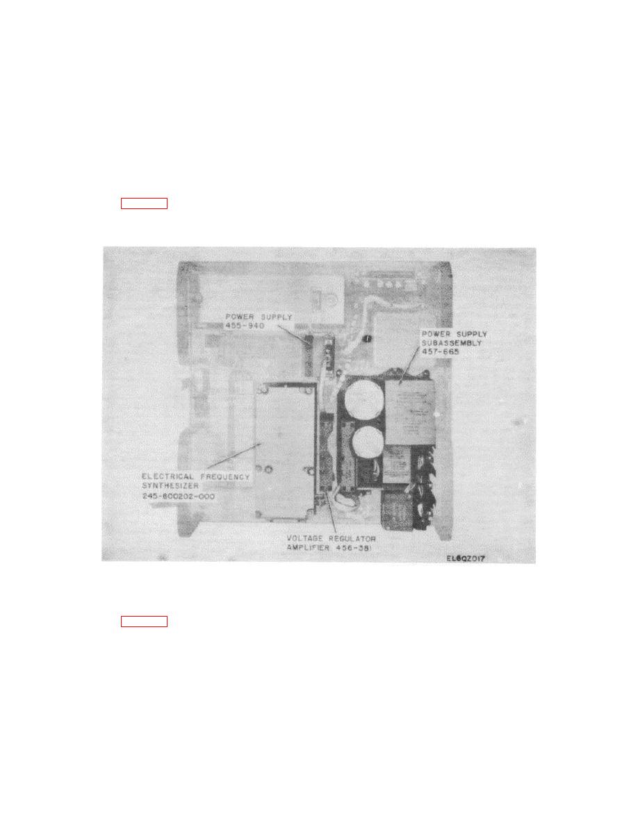
locate power supply subassembly 457-665.
b. Loosen the two captive screws on P2 and
plate to the synthesizer and disconnect P1.
c. Loosen the four captive screws and pull the
disconnect P2 from J4.
c. Loosen the seven captive screws that
synthesizer directly away from the chassis.
d. Carefully
secure the subassembly to the chassis.
position
the
replacement
d. Pull the subassembly directly away from
synthesizer, engage the chassis connector, and tighten
the chassis.
the four captive screws.
e. Carefully position the replacement power
e. Connect P1 and J11 and tighten the
supply subassembly, engage the chassis connector,
captive screw to secure the plate to the synthesizer.
and tighten the seven captive screws.
f.
5-22.
Replacement of Power Supply Subassembly
Connect P2 to J4 and tighten the two
457-665 (fig. 5-14)
captive screws.
a. At the rear of the receiver test facility
chassis,
Figure 5-14. Receiver Test Facility Chassis, Rear View.
5-23.
Replacement of Voltage Regulator Amplifier
d. Carefully position the replacement voltage
456-381 (fig. 5-14)
regulator amplifier, engage the chassis connector, and
a. At the rear of the receiver test facility
tighten the four captive screws.
chassis, locate voltage regulator amplifier 456-381.
5-24. Replacement of Power Supply 455-940 (fig. 5-
b. Loosen the four captive screws that secure
14)
the assembly to the chassis.
a. At the rear of the receiver test facility
c. Pull the assembly directly away from the
chassis, locate power supply 455-940.
chassis.
5-18

 Previous Page
