
TM 11-6625-2398-15-2
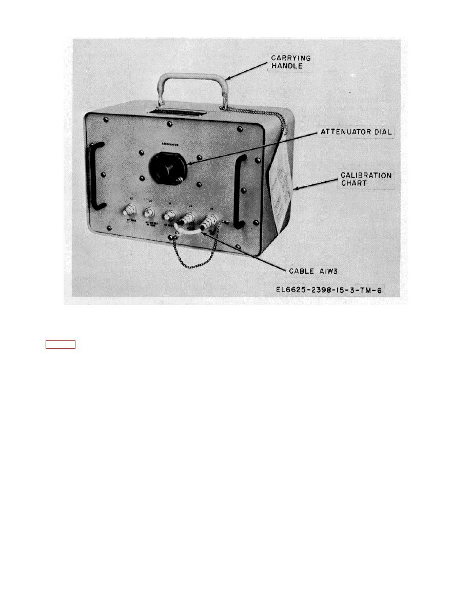
Figure 3-2. Hybrid attenuator 2A1, operating
controls and indicators.
3-2. Hybrid Attenuator 2A1, Operating Control, Cable and Connectors
The following listing provides a description of the control, cable and connectors located on the front panel of hybrid
attenuator 2A1.
Control, cable or connector
Function
ATTENUATOR control AT1
Continuously variable control of the attenuation between ATTEN OUT jack J4
(variable attenuator).
and ATTEN IN/RF DIFF jack J5 (from 0 to 25 db).
ATTEN IN/RF DIFF jack 15 ...........................Permits connection of external equipment to ATTENUATOR AT1.
ATTEN OUT jack J4
Permits connection of external equipment, or the hybrid junction of the hybrid attenuator
to ATTENUATOR AT1.
Cable 2A1W3
Permits series connection of ATTENUATOR AT1 and the hybrid junction by connecting
ATTEN OUT jack J4 to CPLR IN jack J3.
RF IN/OUT jack J1 .
Permits connection of external equipment to the hybrid junction. When used as an input
connection. Rf signals applied at this jack are equally split and appear in attenuated
form (approximately 3 db down) at both RF SUM jack J2 and CPLR IN jack J3.
When used as an output connection, Rf signals applied at either the RF SUM jack J2
or CPLR IN jack J3 appear in attenuated form (approximately 3 db down) at this jack.
RF SUM jack J2
Permits connection of external equipment to the hybrid junction. When used as an input
connection. Rf signals applied at this jack appear (less insertion loss of the cables
and hybrid junction) at RF IN/OUT jack J1. May also be used as an output
connection when RF signals are applied at RF IN/OUT jack J1
Change 1 3-3

 Previous Page
