
TM 11-6625-2398-15-2
CHAPTER 3
OPERATING INSTRUCTIONS
Section I. OPERATOR'S CONTROLS, INDICATORS, AND CONNECTORS
control, indicator, and connector located on the front
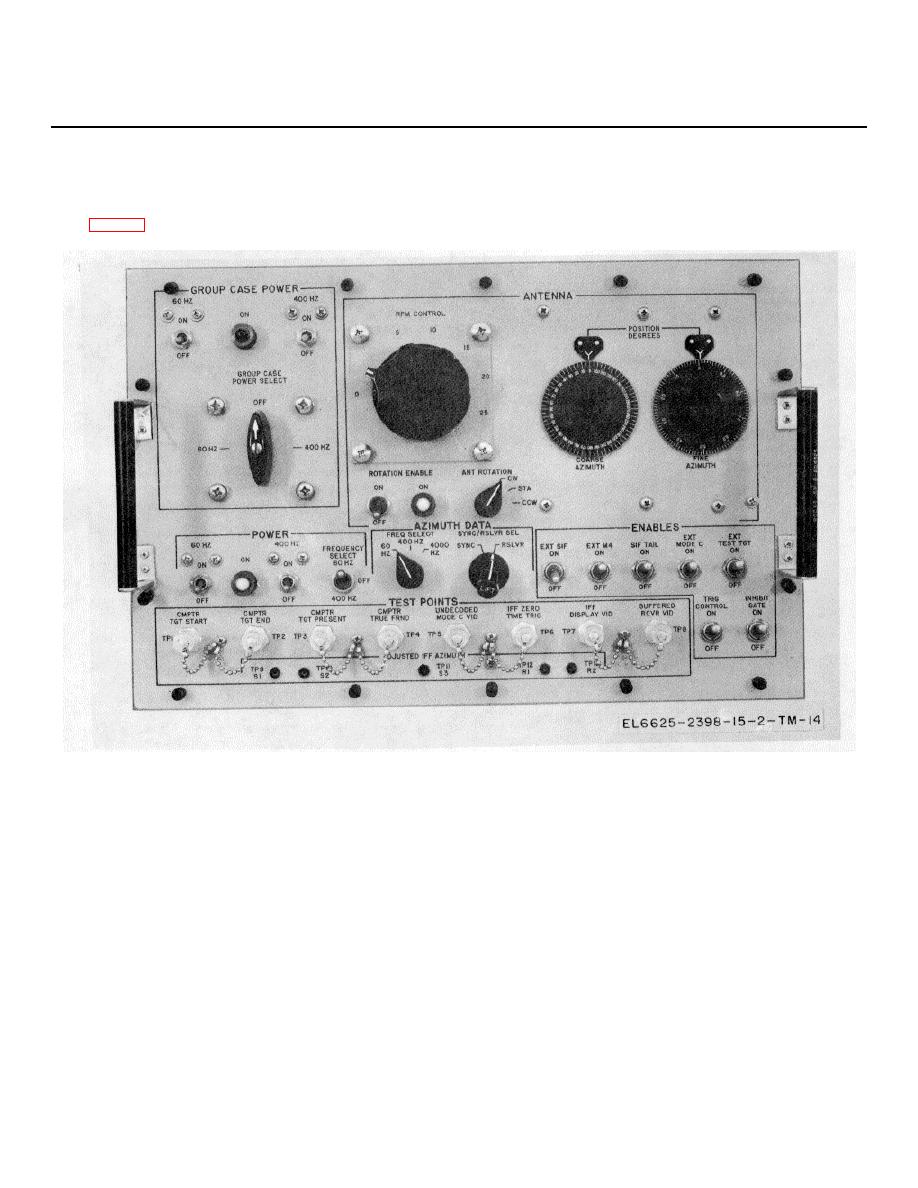
3-1. Interface Adapter Unit 1A1A1 Operating
panel of interface adapter unit 1A1A1.
Controls, Indicators, and Connectors
The following listing provides a description of each
Figure 3-1. Interface adapter unit IAA 1, controls, indicators, and connectors.
Control, indicator
or
connector
Function
GROUP CASE POWER:
60-HZ circuit breaker ................... ................. .When set to ON. 60-Hz power is available to the interface adapter unit,
...............................................................
and the IFF set.
400-HZ circuit breaker .................................. When set to ON, 400-Hz power is available to the interface adapter unit
...............................................................
and the IFF set.
ON indicator Lamp ....................................... When lighted. indicates that 60-Hz or 400-Hz power is being provided to
...............................................................
the IFF set.
GROUP CASE POWER SELECT ............... Selects either 60-Hz or 400-Hz power for application to the IFF set.
switch. ....................................................
When set switch. to OFF, power is not supplied to the IFF set.
3-1

 Previous Page
