TM 11-6625-2398-15-3
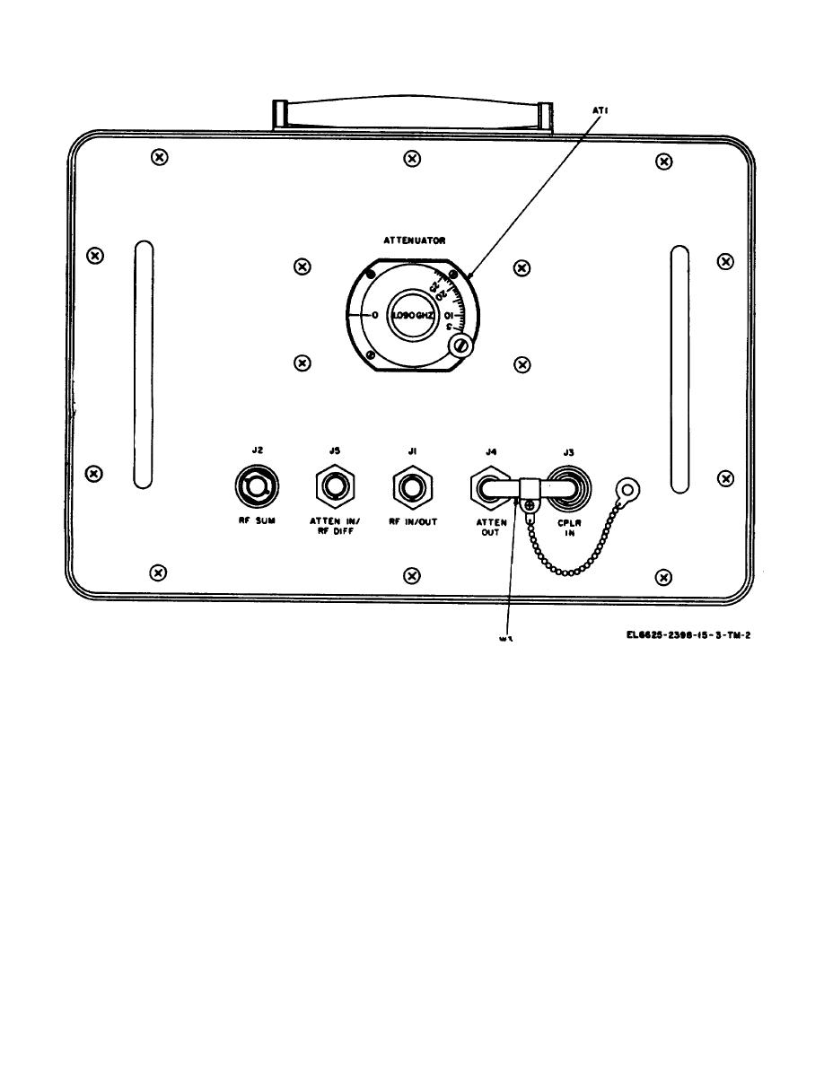
Figure 3-1. Hybrid attenuator A1, operating control, connectors and cable.
Control or connector
Function
Control or connector
Function
DIFF IF
Detected dif-
DET REFL
flected pow-
VIDEO
ference
PWR
er pulses
channel re-
VIDEO jack J1
Permits monitoring of various
MOD PULSE
Modulation
receiver-transmitter signals
pulses
as selected by VIDEO
RCVR VIDEO
Receiver video
switch S1
output
RT VAULT jack J2
Permits monitoring of the
CHAL MON
Detected inci-
fault enable output of the
DET INCI
dent (trnas-
receiver-transmitter.
DENT PWR
mitted) pow-
LVPS MON jack J3
Permits monitoring of the low
er pulses
voltage power supply moni
CHAL MON
Detected re-
tor signal of the receiver-
transmitter.
3-2


 Previous Page
