
TM 11-6625-2398-15-3
the connector for the removed board with the even
pc board with the even numbered side of the extender
board and insert the etched terminals in the connector of
numbered side of the extender board oriented with the
component sides of the pc boards in the balance of the
the extender board.
assembly. Orient the component side of the removed
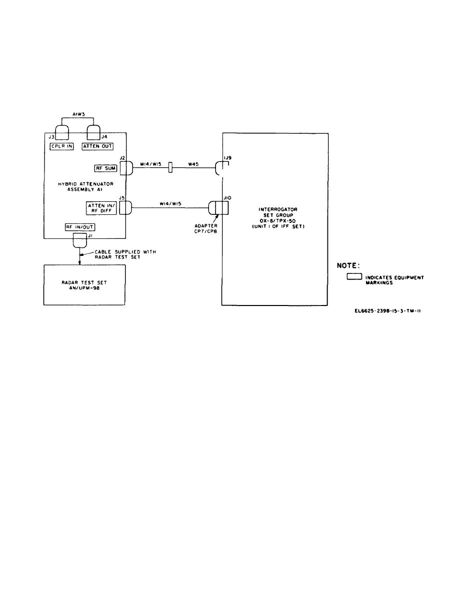
Figure 3-4. Typical hybrid attenuator receiver and
transmitter test connections.
b. Adapters CPI and CP2/CP3/CP4. Adapter CP1
(4) Extender boards A3/A4 are provided with test
points for each etched terminal of the pc board to
permits connection of an OSM type plug to a BNC type
facilitate checking any input or output of the pc board.
plug. Adapters CP2/CP: I/C1'4 permit connection of
The numbers (1 through 44) above the test point
OSM type jacks to BNC type plugs. Typical connection
correspond to the. etched terminal number of the pc
of these adapters is given in the challenge monitor test
board.
I)provided in TM 11-5895-687-35-4.
(5) Extended board A5 provides maintenance
c. Adapters CP5/CP6. Adapters CPS/(CP6 permit
accessibility for the pc boards removed by pc board
connection of selectro jacks to BNC type plugs. Typical
extractor MP1, (2) above. Orient the male connector
connection of these adapters is given in the transmitter
pins of extender board A5 (printed land side down) with
frequency measurement tests provided in TM 11-5895-
the top of the receiver-transmitter assembly. Remove
687-35-4.
the pc board and insert the female pin connector end of
the extender board in the connector for the removed
d. Attenuators AT1/A72. Attenuators AT1/ AT2 are
board. Orient the component side of the removed pc
general purpose 50-ohm 6dB attenuators. Together with
board with the top of the receiver-transmitter assembly.
other uses they can provide isolation during diplexer
Insert the sides of the pc board in the slots of A5 and
adjustment. Typical connection of these attenuators ,D
engage the female connector pins of the pc board with
provided in TM 11-5895-687-35-4.
the male connector pins of the extender board.
3-7

 Previous Page
