TM 11-6625-2398-15-3
Control or connector
Function
Control or connector
Function
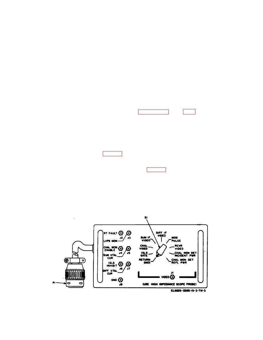
CHAL MON ENABLE jack
Permits monitoring of the
inhibit pulse output of the
J4
challenge monitor enable
receiver-transmitter.
output of the receiver-trans-
DIFF XTAL CUR jack J7
Permits monitoring of the dif
mitter.
erence channel crystal
SUM XTAL INHIBIT jack J6
Permits monitoring of the sum
(mixer diode) current signal
channel crystal (mixed
of the receiver-transmitter.
diode) current signal of the
GND jack J8
Provides the ground return
receiver-transmitter.
for the signal being moni-
ISLS INHIBIT jack 6
Permits monitoring of the isls
tored.
Section II. OPERATION
operation of the test facilities set are contained in
3-3. Types of Operation
a. The test facilities set is used to interconnect
components of the IFF set and to facilitate monitoring of
IFF set component
Technical manual
signals and voltages when the iff set and/or its
Control box
TM 11-5895-687-35-1
components are undergoing test bench maintenance.
Interrogator group case
TM 11-5895-687-35-1
Depending on the availability of bench space and the
Processor
TM 11-5895-687-35-2
expected maintenance workload at a particular
Receiver-Transmitter
TM 11-5895-687-35-4
maintenance activity, the test facilities set and
Synchronizer
TM 11-5895-687-35-3
associated required equipment may be installed and
connected as a semi-permanent test station (para 2-3),
3-4. Connection of Extender Cables
or only those applicable components required for the
particular maintenance task may be set up.
Regardless of the type of operation of the test facilities
set (para 3-3), it is generally necessary to remove one
b. Specific instructions for connecting the IFF set
or more of the iff set components from the interrogator
and required test equipment and accessories, and for
group case to obtain access for maintenance. Cables
performing maintenance on the various iff set
W39, W40, W41, W42 and W43 are provided to extend
components are contained in the technical manuals
the processor, synchronizer and receiver-transmitter
listed below. General instructions for
from the interrogator group case. To connect the
extender cables, first remove the component(s) from the
interrogator group case as
Figure 3-2. Front panel test adapter A2 operating control connectors.
3-3


 Previous Page
