
TM 11-6625-2398-15-3
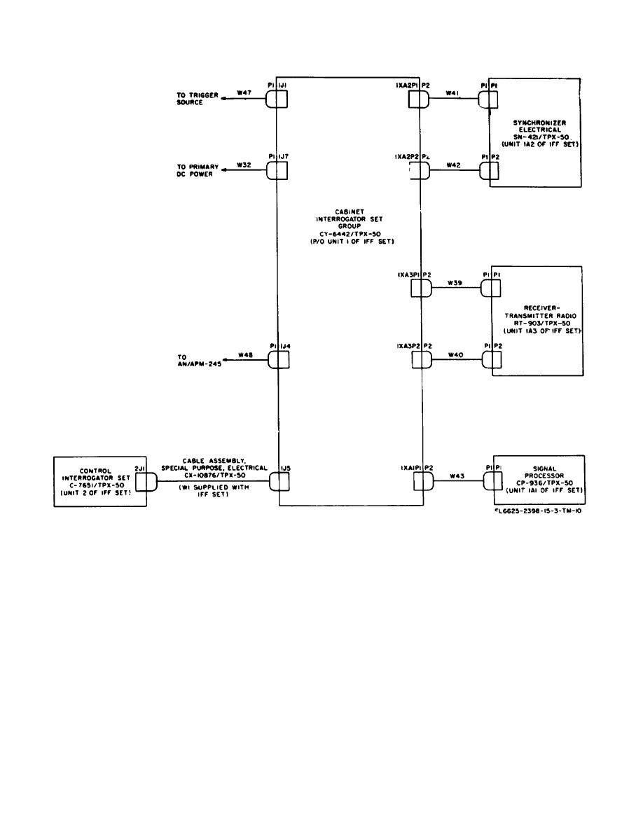
Figure 3-3. Connections of test cables to the IFF set.
other external test equipment to the interrogator group
the AN/APM-245.
case. To establish initial test set-up connections using
the AN/APM-245, connect P1 of cable W48 to
3-9. Operation of Front Panel Test Adapter
COMPUTER VIDEO jack 1J4 on the rear of the
interrogator group case. Connect P1, P4, and P5 of
The front panel test adapter is provided to facilitate
cable W48 to the EXTERNAL TRIGGER, TEST WORD,
monitoring of various signals of the receiver-transmitter.
and DIS PARITY connectors respectively, on the
Signals available at multipin TEST connector 1A3J1 of
AN/APM-245. Connectors P2 and P6 of cable W48
the receiver-transmitter are either routed directly to
may be used for monitoring the mode 4 reply output of
individually labeled test jacks on the front panel test
the iff set and applying a simulated mode 4 time
adapter, or are routed through the VIDEO selector
decoded video signal input to the iff set, respectively,
switch to the VIDEO jack. To operate the front panel
using external test equipment. Refer to TM 11-5895-
test adapter, proceed as follows:
687-35-3 for detailed connections of W48 and
procedures for use of
a. Connect P1 of the front panel test adapter cable
to TEST connector 1A3J1 on the front
3-5

 Previous Page
