
TM 11-6625-2414-15
2-8. Operation--Backlash
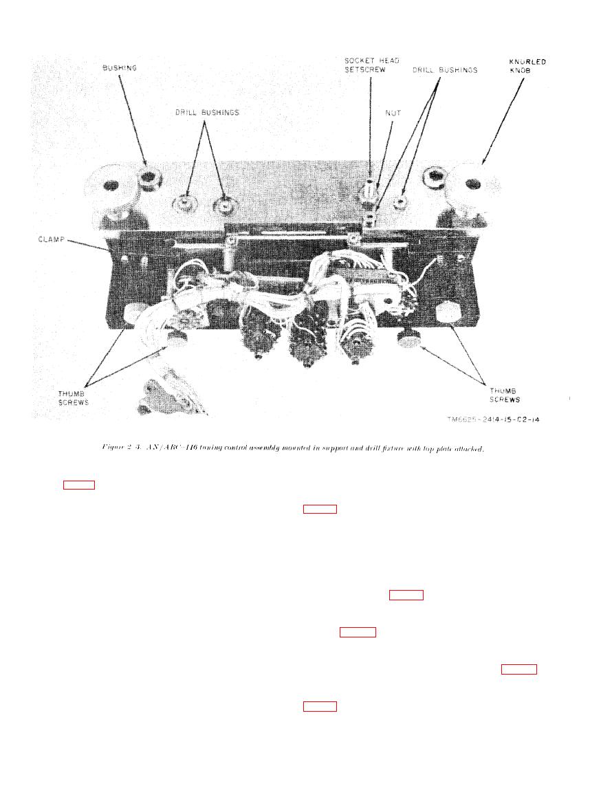
Fixture
thumbscrews after positioning the hole in the A plate
over the diamond pin of the fixture and the shaft of
shaft assembly MP57 into the split clamp of the fixture
NOTE
The following procedure must be performed
d. Select the arm and shaft assembly of the fixture
to properly position MP59 on the shaft of S5
that corresponds to the switch rotor color ("red" or
whenever switch S5 and/or gear MP59 is
"black"), and insert the flatted shaft into the guide
replaced in Radio Set AN/ARC116.
bushing near the pointer. Rotate the arm and shaft
a. Refer to paragraph 410 j, TM 11-5821-261-35
assembly counterclockwise until the hole in the arm is
and disassemble the tuning control assembly, as
directly over the guide bushing on the left side of the
required, to separate the A plate (A1A1MP21M1)
fixture's face plate (fig. 1-8 @ and 2-4). The tip of the
assembly, with attached switches and gears, from the
shaft should then slip into the switch rotor.
chassis and plate assembly; then remove defective
e. Insert a pin through the hole in the arm and guide
gear MP59 and/or switch S5.
bushing (fig. 1-8 @).
b. If required, assemble a new S5 assembly to the
f. Position the pointer in the approximate center of
A plate, then preset either the new or existing S5 wiper
the scale and tighten the pointer thumb nut.
towards terminal 9 of the switch decks, and observe the
color of the switch rotor inside the rear plate of the
Loosen the pointer thumb nut and gently rotate the
switch assembly.
pointer clockwise until increased resistance is met
c. Position gear MP59 over the shaft of S5. Do not
tighten the gear to the shaft with setscrews. Secure
the A plate to the fixture with the two clamps and
Change 2

 Previous Page
