TM 11-6625-2398-14-4
is used, and 25 No. 20 pins of which one is used.
(11) Insert cable and parts into connector body.
Care should be taken to insure that knife edge of braid
Connectors P2 through P5 (SM-B-604273-1) are
clamp is properly seated in "V" groove gasket. Tighten
Amphenol, BNC male connectors part No. 31-232.
b. Repair of Cable. The following procedure is to
clamp nut securely to complete assembly (fig. 7-4, view
G).
be performed when a new cable assembly is to be
(12) Using heat gun, shrink tag marker.
fabricated. To replace plug P1 perform (1) through (23)
(13) Attach dust cover to cable with cable
below. To replace plugs P2 through P5, perform (24
clamp.
through 46) below.
(14) Calibrate cable in accordance with
(1) Cut a section of cable (SM-D-604261) 96
procedures contained in TB 11-6625-2398-35.
inches in length.
(2) Place tag marker, boot, one 6-inch piece
7-11. Repair of Cable 1A1W5 (SM-D-986522)
a. Description of Cable.
of heat shrink sleeving and two 5-1/4-inch long pieces of
Cable lAIW5 is a
heat shrink sleeving over outside of cable jacket.
multiconductor (SM-D-604261) cable having four
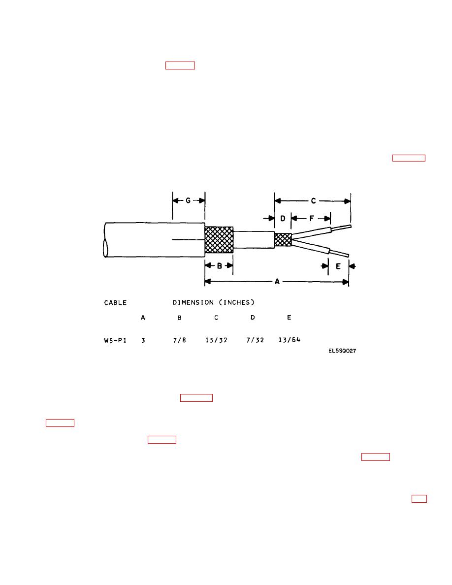
(3) Strip 3 inches of outside cable jacket from
conductors and five connectors. Connector P1 (SM-A-
end of cable which will connect to P1 (fig.
604383-1) is a NSA connector, part No. ON089559-1,
dimension A).
containing eight coaxial pins of which four are used for
RF-180B/U cable, four No. 16 coaxial pins of which one
Figure 7-5.Stripping Details, Cable 1A1W5P1.
(4) Trim 2-1/8 inches of braid from end of
(9) Slide outer ground ring over cable wires
cable leaving 7/8-inch of braid exposed (fig. 7-5,
and braid so that outer ground ring is centered over inner
dimension B).
ground ring.
(5) Strip 15/32-inch from jacket of coaxial
(10) Insert hair pinned end of wire (refer to (7)
above) between outside ground ring and cable braid.
cable (fig. 7-5, dimension C).
(6) Trim 1/4-inch of braid from coaxial cable
(11) Using crimping tool, crimp outer ground
leaving 7/32-inch of braid exposed (fig. 7-5, dimension
ring, black wire, and inner ground ring.
D).
(12) Strip 13/64-inch of insulation from each
(7) Cut a 3-1/2-inch length of 22AWG black
wire which will be connected to P1 (fig. 7-5, dimension
wire and strip 1/2-inch and 3/8-inch of insulation from the
E).
wire ends. Hairpin the end of the black wire which has
(13) Using crimping tool MS3191-4 with
11/2-inch of insulation removed.
MS319T positioner, crimp pins supplied with connector
(8) Slide inner ground ring over cable wires
P1 onto exposed wire ends.
and under cable braid.
(14) Insert pinned wires into connector (fig.
7-6


 Previous Page
